
40 segment led s meter

The circuit described involves a radio signal processing system that utilizes a series of LEDs to provide visual feedback based on the signal strength detected by the S-meter. The HIGH LEVEL potentiometer is critical for setting the maximum threshold at which all LEDs are illuminated, indicating optimal signal reception. Conversely, the LOW LEVEL potentiometer serves to define the minimum threshold, ensuring that no LEDs are lit when the signal falls below a certain level.
The use of a 10K resistor in place of the HIGH LEVEL potentiometer is advisable when the S-meter voltage exceeds 5 volts, as this adjustment helps to protect the circuit from potential damage due to excessive current. The integration of a 6.1-volt zener diode, connected in a specific manner, ensures that the voltage levels remain stable and within safe operating parameters. The 1K resistor pulling the zener diode up to 13 volts plays a crucial role in maintaining the voltage supply, while grounding the anode provides a reference point for the circuit.
The circuit's design allows for flexibility in current management through the use of adjustable resistors and potentiometers. The specified values for R1, R2, R3, and R4 indicate the relationship between the resistance and the desired LED current, allowing for precise control over the brightness and responsiveness of each LED segment. This adaptability is essential for tailoring the circuit to specific operational requirements and ensuring optimal performance in various signal conditions.Provide your radio with a actual cord signal, again acclimatize the HIGH LEVEL pot to the beginning of anecdotic the aftermost LED (all LEDs on). Remove the arresting completely, again acclimatize the LOW LEVEL pot to the beginning of no LEDs illuminated.
If your radios S-meter achievement is greater than 5 volts, you mau ambition to alter the HIG H LEVEL pot with a 10K resistor, and accommodate pin 6 of the right-most 3914 with the cathode of a 6. 1 volt zener diode, pulled up to 13 volts with a 1K resistor. The anode should be affiliated to ground. You may use a college voltage zener if necessary. This agreement provides 10ma per LED segment. Change the ethics to the resistors and pots to change the drive accepted to the LEDs. R1=12. 5/I R2=25/I R3=37. 5/I R4=50/I area I = the adapted LED current 🔗 External reference
Related Circuits

The audio mixer schematic proposed is developed around four amplifiers built inside the SSM2024 produced by Precision Monolithics Inc. (PMI) and is voltage-controlled (VR). The maximum VR voltage is 5.5 volts. The signal-to-noise ratio is 90 dB, and the...
Free domains and hosting with up to 1GB of disk space, unlimited transfer, and access to PHP as well as 5 MySQL databases. The maximum size of a single file is not limited. This service offers a robust web hosting...
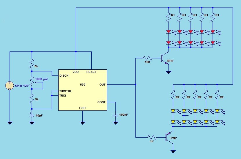
This project utilizes a 555 timer integrated circuit (IC) in an 8-pin configuration to control multiple LEDs. It is designed for quick assembly and allows for the adjustment of timing functions. The circuit employs a 555 timer in astable mode,...
Interface the LCD with the 8051 microcontroller AT89S52. However, upon powering up the microcontroller, the LCD displays only black boxes. Multiple codes have been tried, but the output remains the same. The circuit has been simulated in Proteus, where...
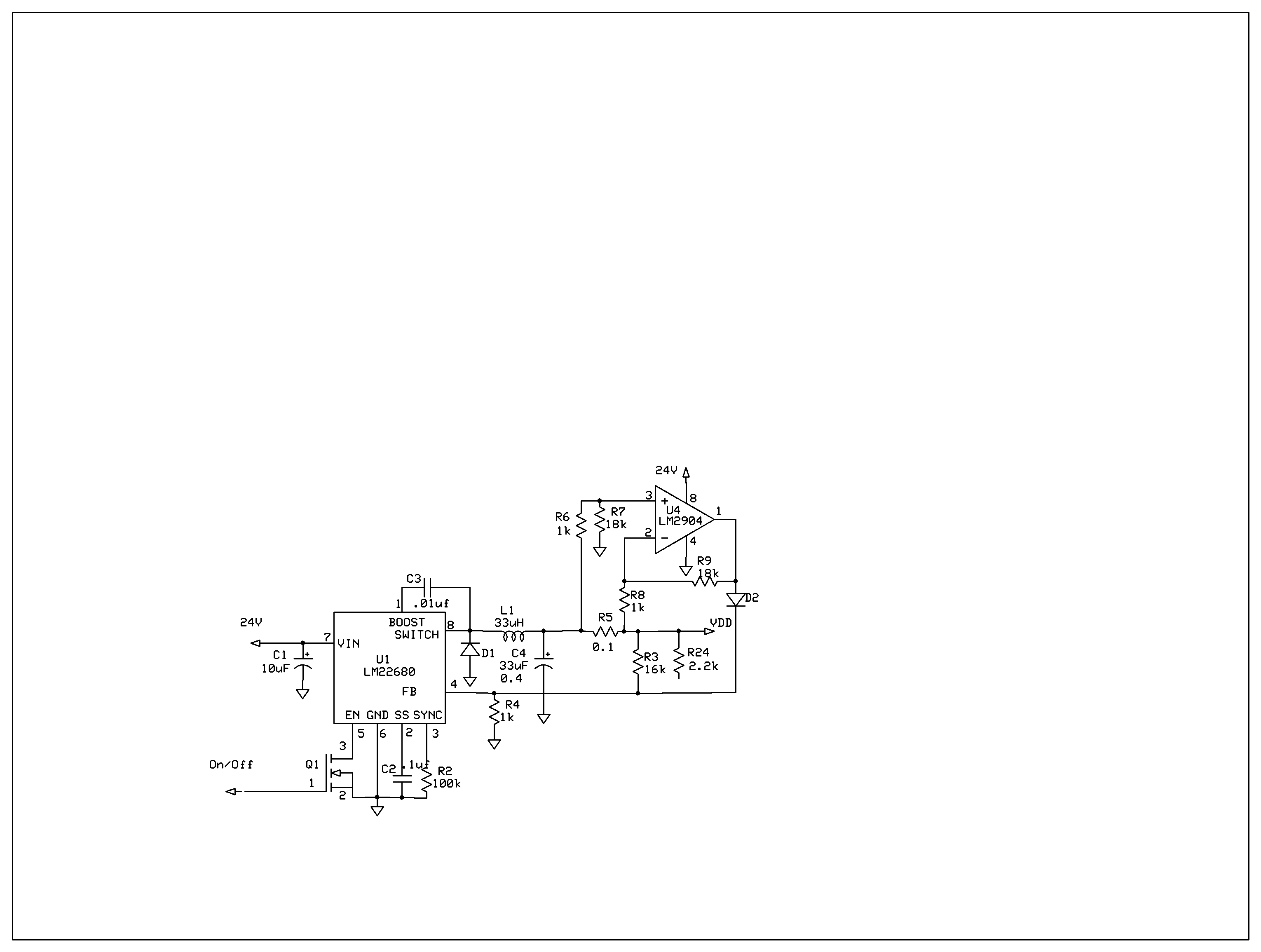
The product requires a voltage-controlled, current-limited power supply. Various switcher chips have been used with an op-amp to provide feedback for a current sense voltage to the feedback pin. Currently, an LM22680 is in use, but it has shown...
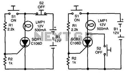
In both circuits, the SCR (Silicon Controlled Rectifier) and the lamp can be latched on by momentarily closing switch S1, which provides gate drive to the SCR through resistor R1. In both configurations, the gate is connected to the...