
Power Path Management Battery Charger

Power management in electronic systems is critical, particularly in applications that necessitate simultaneous operation and battery charging. This dual functionality can lead to complex interactions between the system load and the charging circuit.
In a typical configuration, a power management integrated circuit (PMIC) is employed to oversee the power distribution between the system and the battery charger. The PMIC ensures that the system receives adequate power while the battery is being charged, preventing any interruptions in operation.
The schematic typically includes a battery management system (BMS) that monitors battery voltage, current, and temperature to optimize charging cycles and prolong battery life. The charger circuit can be a linear or switch-mode power supply, depending on the efficiency requirements of the application.
When the system is operational, the PMIC regulates the power drawn from the battery and the charger, allowing for seamless transitions between battery power and line power. This is often achieved through the use of power path management techniques, which ensure that the system can function without interruption even if the charger is disconnected.
Additionally, protection circuits are incorporated to safeguard against overvoltage, overcurrent, and thermal conditions, which could damage the battery or the system. These features are crucial in applications such as portable devices, where reliability and safety are paramount.
Overall, the design of a power management system that supports simultaneous operation and charging requires careful consideration of the interaction between the system load and the charging circuitry to ensure optimal performance and safety.Powering the system is required by many applications while charging the battery simultaneously. Interaction between the system and charger may result in a.. 🔗 External reference
Related Circuits
A compact and portable 12V solar power inverter circuit designed to provide illumination. This proven design converts 12V DC from a storage battery. This 12V solar power inverter circuit is engineered to transform direct current (DC) from a solar battery...
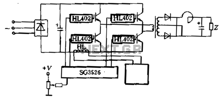
Applications are provided to complete the four-piece HL402 switching power supply system diagram, which drives four power IGBT switching power supplies. The IGBT drive pulse is generated by the SG3526. The HL component serves as a current sensor, utilized...
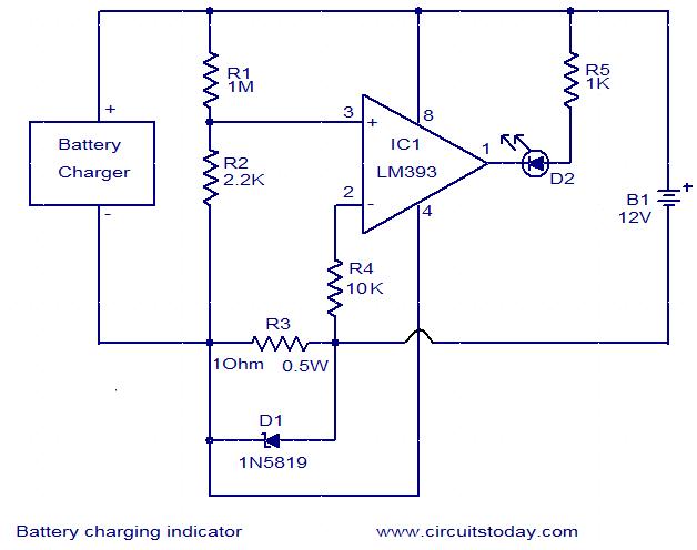
This simple circuit can be used to monitor whether a battery is charging. The voltage comparator IC LM393 is the core component of this circuit. The LED D1 will remain ON whenever there is at least 25 milliampere current...
This circuit utilizes the TA7222AP to amplify audio signals. The cost is only $0.99, and it can provide 5.8 watts with muting control. The power supply can be in the range of 8-12 VDC, making it suitable for applications...
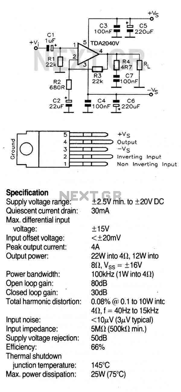
This circuit utilizes the TDA2040V, a monolithic power amplifier integrated circuit designed for high-quality, class AB audio amplification. It typically delivers 22W of output power into a 4-ohm load with a distortion level of 0.5%, powered by a 32V...
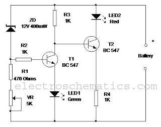
This circuit monitors the charging process of a 12 Volt Lead Acid or Tubular battery. The LED status indicates whether the battery is charging and signals when it reaches a full charge. It can be integrated into various battery...