
Power Power Outages after the call prohibit a re-closure circuit

The described circuit addresses the challenge of managing electrical appliances during power outages, particularly in scenarios where re-closure is necessary after a call. The primary concern is to prevent accidental usage of appliances that could lead to hazardous situations. The circuit employs relays or contactors, which are conventional methods for controlling electrical loads. However, relays have a significant drawback due to their coil power consumption, which can be problematic in energy-sensitive applications.
In cases where the load power is high, contactors become essential. While effective, contactors introduce additional complexities, including increased size, installation challenges, and operational noise, which can be undesirable in residential or quiet environments.
To mitigate these issues, the implementation of dual thyristors as non-contact switches presents a modern solution. Thyristors are semiconductor devices that can control high voltage and current without the mechanical movement associated with relays and contactors. This non-contact operation leads to reduced power consumption, lower noise levels, and improved reliability, as there are no mechanical parts to wear out over time.
The proposed circuit design would typically include a control logic that monitors the power status of the grid and the state of the appliances. Upon detecting a power outage, the circuit would engage the thyristors to disconnect the load. When power is restored, the thyristors would remain off until a manual reset or a specific condition is met, ensuring that appliances are not inadvertently turned on.
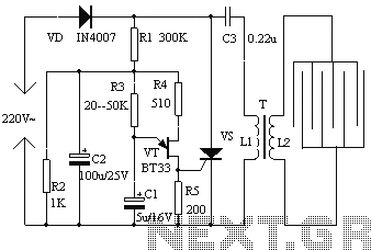
In conclusion, the integration of dual thyristors into the circuit design enhances the overall performance by providing a reliable and efficient method for managing electrical loads in the event of power interruptions, thereby improving safety and reducing the risk of accidents.Power outages after the call prohibit re-closure circuit, can avoid the use of electrical appliances after the power grid and forgot to turn off electricity, then call caused an accident when. Use relays or contactors can be easily shown 13-77 (a) shown below, but the relay coil to coil power consumption, and when the load power is large, the need to use contactor control, not only cumbersome but also noise. If dual thyristor as a non-contact switch, can solve the problem,
Related Circuits
In the first circuit, the BC548 transistor is configured as a Colpitts oscillator, with the frequency being adjusted through the use of a crystal. A high-quality crystal will produce high-frequency oscillations, and the output at the collector is rectified...
The danger always exists when fuel gases such as propane or natural gas are confined to a small area. The toxic gas alarm utilizes a tin-oxide semiconductor. A coil of thin wire is heated by a 12 V battery...
The electronic fly disinfestation system is a simple and effective device designed to eliminate flies using electrical means. The apparatus, as depicted in Figure 1, operates on 220V mains power supplied directly through a rectifier. It utilizes a relaxation...
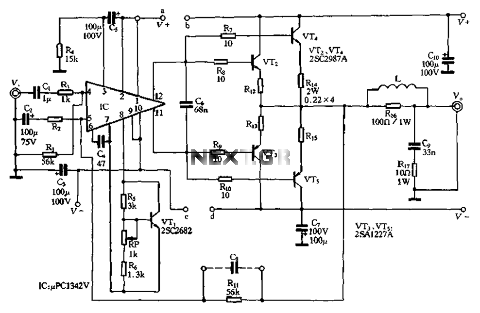
The pLPC1342V and NE are two companies involved in a tube amplifier circuit utilizing 2SA1227A and 2SC2987A transistors, achieving a maximum output power of up to 120W with a cutoff frequency of up to 500 MHz. The circuit, illustrated...
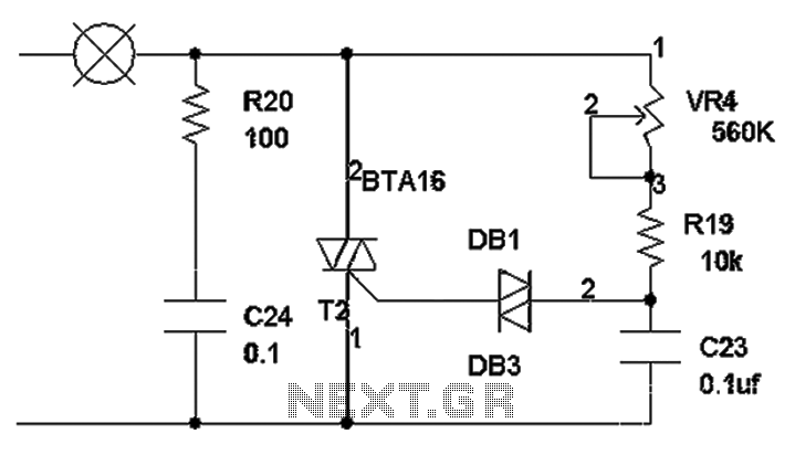
The TRIAC dimmer circuit diagram operates on the principle that a 220V lamp is controlled through the charging of capacitor C23 via resistors VR4 and R19. The charging time is influenced by the values of VR4 and R19, where...
The figure illustrates a schematic for an oscillator amplitude-control servo system. The circuit establishes a closed-loop system that provides a fixed and adjustable peak-to-peak amplitude AC signal centered around 0 V. A 1 kHz sine wave, designated as AC_INPUT,...