
Parallel DC power supply circuit
The DC power supply circuit is designed to convert alternating current (AC) to direct current (DC) while ensuring stable voltage output and adequate current limiting for safe operation. The shunt resistor is integrated into the circuit to measure current flow, enabling real-time monitoring and protection against overcurrent conditions.
The rectifier section utilizes diodes arranged in a bridge configuration to efficiently convert the incoming AC voltage to pulsating DC. Following the rectifier, a filter capacitor smooths the output voltage, reducing ripple and providing a more stable DC voltage.
Voltage regulation is achieved through a linear voltage regulator or a switching regulator, ensuring that the output remains at a constant 10V, regardless of variations in input voltage or load conditions. Current limiting is incorporated to prevent damage to the circuit components and the load by restricting the maximum current output.
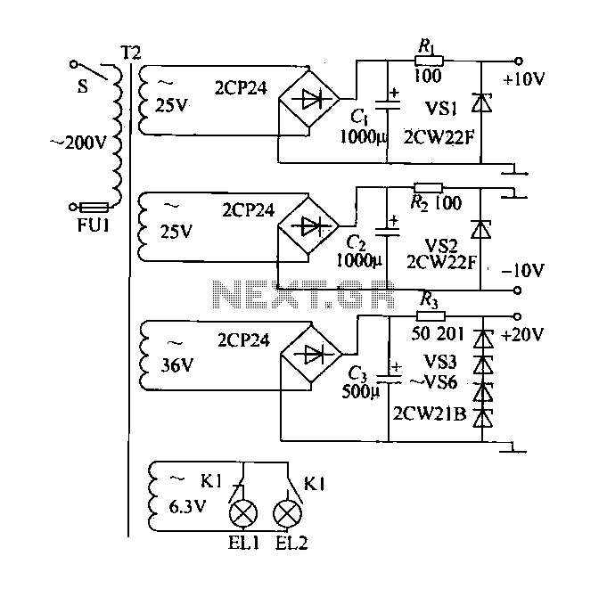
The circuit also includes a 3V indicator system, comprising two indicator lights (EL1 and EL2), which signal the operational status of the machine. These indicators are controlled by a relay circuit that responds to the machine's operational state, illuminating EL1 when the machine is running and EL2 when it is stopped. This feature enhances user awareness and operational safety.
Overall, this DC power supply circuit is characterized by its simplicity, cost-effectiveness, and functionality, making it suitable for a wide range of applications in various electronic devices and systems.DC power supply with shunt, the rectifier, filter, current limiting, voltage regulation, 10V voltage outputs, the circuit is simple, low cost, to meet the requirements of vario us applications, as shown in FIG. FIG. 6. 3V indicator EL1, EL2, respectively, indicating the machine running and stopping, by the relay control circuit.
Related Circuits
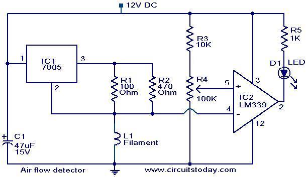
The filament of an incandescent bulb serves as the sensing component of the circuit. When there is no airflow, the resistance of the filament is low. In contrast, when airflow is present, the resistance decreases because the moving air...
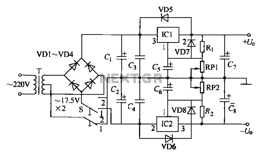
The circuit utilizes a three-terminal adjustable integrated voltage regulator. It includes a gear set and a power supply voltage that is stepped down using a transformer rated at 17.5V x 2 AC. The output voltage after the bridge rectifier...
Free domains and hosting with up to 1GB of disk space, unlimited transfer, and access to PHP as well as 5 MySQL databases. The maximum size of a single file is not limited. This service offers a robust web hosting...
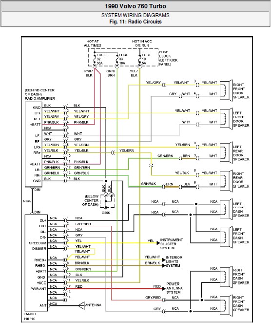
The following document contains the system wiring diagram of the radio circuit for the Volvo 760 Turbo 1990. Please note that this is a system wiring diagram, not a schematic diagram. Download the radio circuit system wiring for the...
The purpose of this circuit is to animate shop windows using a capacitive sensor placed behind a postcard-like banner. The card is positioned against the glass inside the shop window, allowing visitors to activate the relay by placing their...
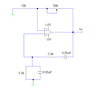
An operational amplifier-based sine wave generator circuit, commonly known as a Wien bridge oscillator, is recognized for its simplicity and stability. The Wien bridge oscillator connects the Wien bridge circuit between the amplifier's input and output terminals. The bridge...