
1990 Volvo 760 Turbo Radio circuit

The system wiring diagram for the radio circuit in the Volvo 760 Turbo 1990 provides a comprehensive view of the electrical connections and components involved in the radio system. This diagram is essential for understanding how the radio integrates with the vehicle's electrical system, including power supply, ground connections, and signal paths.
Key components typically illustrated in this wiring diagram may include the radio unit itself, speakers, antenna, and any additional controls such as the dashboard interface. The diagram will indicate the power source for the radio, which is usually connected to the vehicle's battery or ignition switch, ensuring that the radio operates when the vehicle is in use.
Ground connections are also critical in this diagram, as they ensure that the radio functions correctly without interference or noise. The wiring for the speakers will show how they are connected to the radio, detailing the positive and negative leads that must be correctly matched for optimal audio performance.
Furthermore, the system wiring diagram may include color codes for the wires, which assist in identifying the correct connections during installation or troubleshooting. Understanding the layout and connections presented in this diagram is vital for technicians and enthusiasts working on the audio system of the Volvo 760 Turbo 1990, allowing for accurate repairs or upgrades to be made.The following document contain the system wiring diagram of Radio circuit for Volvo 760 Turbo 1990. Please take a not that this is system wiring, not schematic diagram. Download Radio circuit system wiring for Volvo 760 Turbo 1990 HERE.. 🔗 External reference
Related Circuits
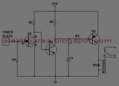
This document describes a series of touch switches that utilize only three transistors. These touch-based transistor switches can activate a load simply by the user touching a metal plate. They are designed to directly switch a relay, enabling operation...
The following circuit illustrates a 2500W Phase Control Circuit Schematic. Features include a ground-tied trigger output that is disabled, and a low voltage input. The 2500W Phase Control Circuit is designed to regulate the power delivered to a load by...
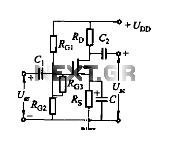
FET several basic bias circuit - self-bias voltage divider circuit The self-bias voltage divider circuit is a fundamental configuration used in Field Effect Transistor (FET) biasing. This circuit employs two resistors to create a stable bias voltage for the transistor's...
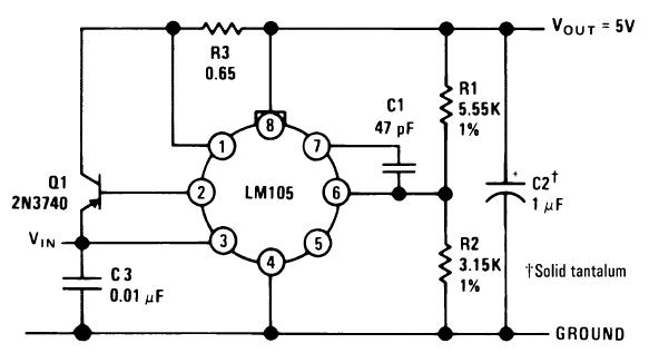
A single diffused, wide base transistor, such as the 2N3740, is recommended due to its reduced tendency to cause oscillation issues compared to double diffused, planar devices. Additionally, it exhibits greater reliability under overload conditions, and low-cost options are...
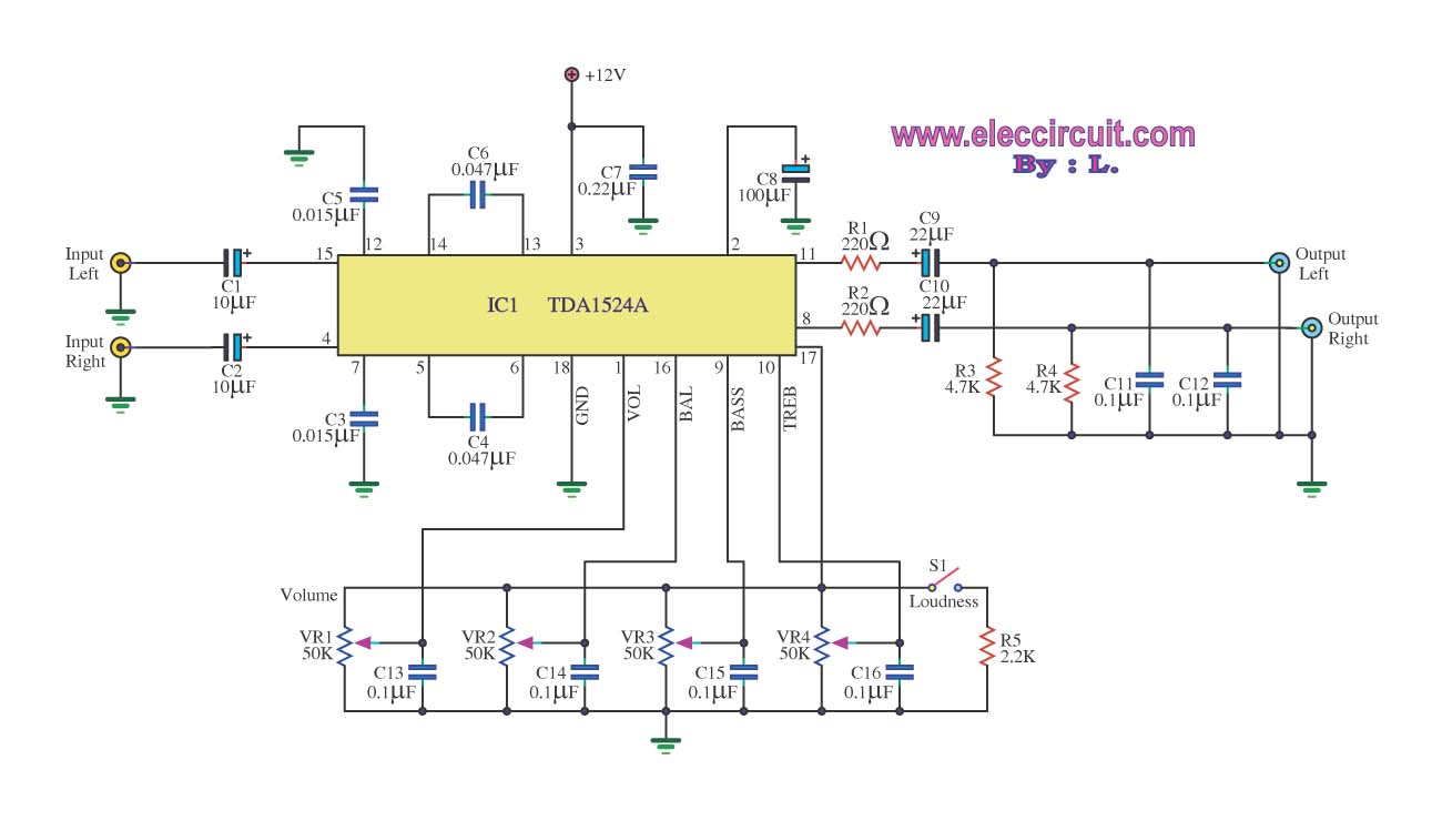
The stereo tone control circuit utilizes the integrated circuit TDA1524A. This IC serves as the central component in the design. The TDA1524A is a versatile integrated circuit designed for audio applications, particularly in tone control systems. It features a dual-channel...
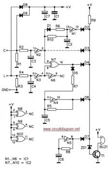
The circuit is designed to ensure that the headlights or side lights are automatically switched off after the ignition contact is turned off. This prevents the occurrence of a dead battery due to headlights being inadvertently left on. The circuit...