
Power Supply +50V 3A stabilized and regulated

The described circuit functions as a regulated power supply capable of delivering an output voltage ranging from +40V to +60V with a maximum current output of 3A. The design emphasizes the need for stabilization in the output voltage, which is critical for applications requiring consistent performance under varying load conditions.
The circuit likely incorporates a linear voltage regulator or a series of transistors configured to manage the voltage output effectively. The mention of Q1 suggests a transistor-based design, which acts as the primary control element in regulating the output voltage. It is essential to select a transistor rated for high voltage and current to ensure reliable operation within the specified parameters.
To manage heat dissipation, particularly when outputting voltages below +50V, a large heatsink is necessary for Q1 to prevent thermal overload. The choice of heatsink should be based on the thermal resistance required to maintain the junction temperature of the transistor within safe limits, considering the expected load current.
For voltages exceeding +50V, the circuit's stabilization performance diminishes, indicating that the design may require additional components such as feedback loops or compensation networks to enhance stability at higher output levels. This could involve using operational amplifiers or additional transistors to improve regulation and minimize ripple in the output voltage.
Overall, careful attention to component selection, thermal management, and circuit layout is essential to ensure that the power supply performs reliably across its specified voltage range while providing the necessary current output.Many times we needed a stabilized, together regulated power supply and high relatively output voltage. These specifications him it cover our circuit. It `s a circuit that can give in his exit + 40V until + 60V 3A, with simultaneous stabilization. The materials that use is very simple and will not exist difficulties in the manufacture, is enough you are careful certain points.
1 ] For output voltages smaller of + 50V until + 40V, the Q1 is hot enough, so that it needs one big heatsink. 2]For output voltages bigger of + 50V up to + 70V, the stabilization is not satisfactory. 🔗 External reference
Related Circuits
A power source providing 2.5V DC at 10µA is utilized to drive a pager motor. The motor activates between 2.3V and 2.5V, and deactivates between 1.2V and 1.5V. The circuit design has been breadboarded by multiple individuals, showing consistent...
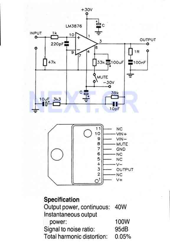
This Circuit is based on the LM3876. A 11-pin plastic package IC with high performance audio power amplifier, an output mute function which can be used to eliminate switch-on and switch-off "thumps" to the loudspeaker load. It is capable...
The following circuit illustrates an Elektroblock circuit diagram utilizing a 12V power supply. Features include various control and monitoring functions, with the specification of an 18 A LAS 1218 component. The Elektroblock circuit is designed to operate with a 12V...
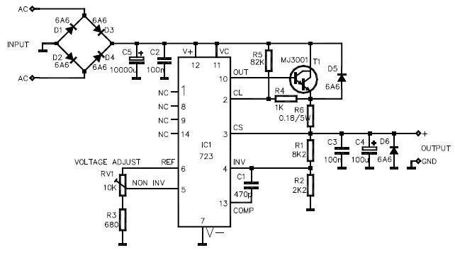
This LM723 variable power supply circuit design is a straightforward variable power supply capable of delivering an output voltage ranging from 8 to 30 volts, with a maximum output current of 3 amperes. The circuit features a low output...
The combination of controller IC LM4651 and LM4652 Class D MOSFET power amplifier IC provides a high-efficiency solution suitable for powered speakers, subwoofers, and car amplifiers. The LM4651 is a fully integrated conventional pulse width modulator (PWM) driver, which...
The 555 is wired as an astable and the capacitor is charged only through the 4.7Kohm trimmer (notice the diode) and discharged only through the 2.2 Kohm trimmer, making the duty cycle fully adjustable. The square wave is then...