
ElektroblockCircuit Using 12V Power Supply

The Elektroblock circuit is designed to operate with a 12V power supply, which is a common voltage level in many electronic applications. The circuit incorporates an 18 A LAS 1218 component, which is likely a power switch or relay that can handle significant current loads. This component is essential for controlling higher power devices within the circuit.
The circuit diagram typically includes various control and monitoring functions, which could involve sensors, indicators, and control switches. These elements work together to provide real-time feedback on the system's performance and operational status. For instance, the inclusion of LEDs can indicate the operational state of the circuit, while sensors may monitor parameters such as temperature or current flow.
To ensure proper operation, the circuit should be designed with appropriate protection mechanisms, such as fuses or circuit breakers, to prevent damage from overcurrent conditions. Additionally, filtering capacitors may be included to stabilize the power supply and reduce noise, enhancing the reliability of the circuit.
Overall, the Elektroblock circuit is a versatile design suitable for various applications where control and monitoring are essential, and it leverages the robust performance characteristics of the LAS 1218 component to manage significant electrical loads efficiently.The following circuit shows about Elektroblock Circuit Diagram Using 12V Power Supply. Features: Other control and monitoring functions, The 18 A LAS 1218 .. 🔗 External reference
Related Circuits
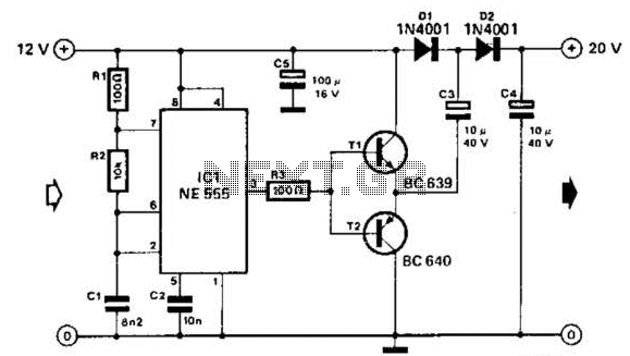
Using a 555 timer and voltage doubler, this circuit will supply over 50 mA at 20 V DC. Transistors T1 and T2 act as power amplifiers to drive the voltage doubler. The frequency of operation is approximately 8.5 kHz. The...
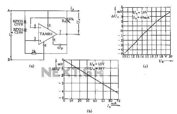
The regulator circuit adjusts the output voltage based on the potentiometer Rp and exhibits linear regulation characteristics. The output voltage Ua varies with the load current Ia, ranging from 0 to 70 mA, as illustrated in Figure (C) for...
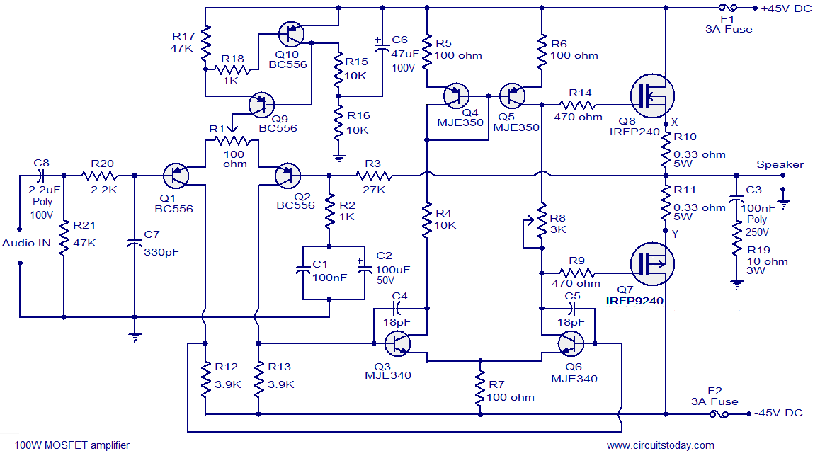
Hi-fi 100W MOSFET power amplifier circuit. Operates from a 45V dual supply. Delivers 100W to an 8-ohm speaker and 160W to a 4-ohm speaker, with low distortion. The Hi-fi 100W MOSFET power amplifier circuit is designed to provide high-quality audio...
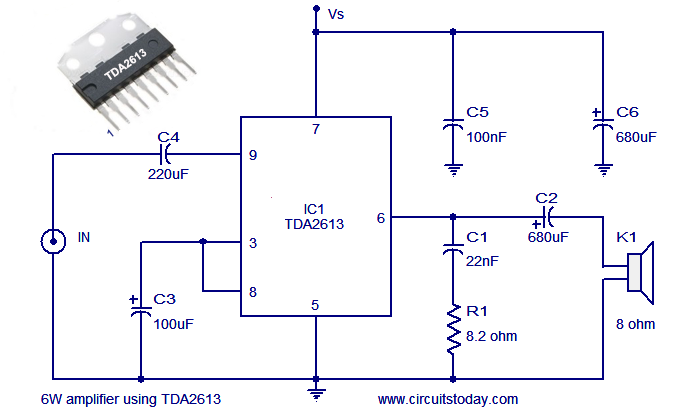
A simple and easy-to-build Hi-Fi audio power amplifier circuit is presented here. This 6-watt Hi-Fi audio amplifier circuit utilizes the TDA2613 integrated circuit (IC). The circuit design employs the TDA2613, which is a high-performance audio amplifier IC known for its efficiency...
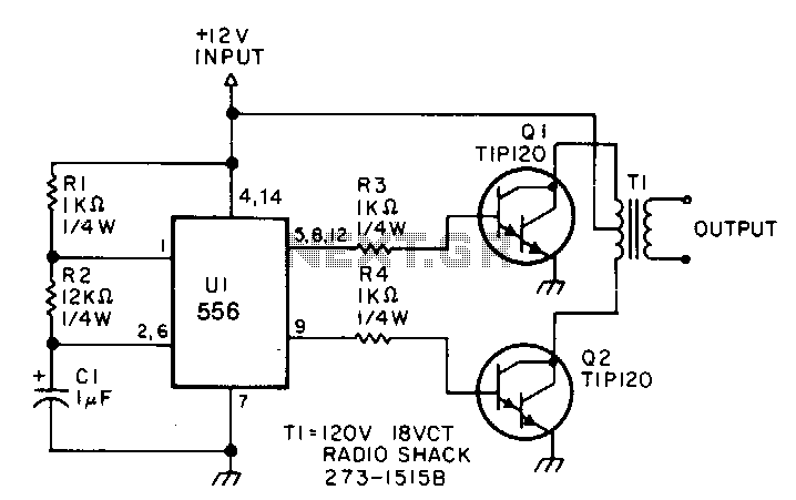
This low-power inverter utilizes only nine components to convert 10 to 16 VDC into a 60 Hz, 115 V square-wave output suitable for operating AC equipment with a maximum power of 25 W. The initial section of the 556...
Designing a wide-range variable power supply using a linear regulator is straightforward; however, it suffers from poor efficiency when regulating a constant 60-volt source. A wide-range variable power supply can be implemented using a linear regulator, which allows for adjustable...