
Power Supply for Preamplifiers (Revision A)
")
The updated version of the P05 circuit incorporates adjustable voltage regulators, which significantly enhance the design's versatility and performance. The adjustable regulators, such as the LM317 or similar, allow users to set the output voltage to their desired level by using external resistors to configure the feedback loop. This feature is particularly advantageous for applications requiring precise voltage levels, such as in laboratory power supplies or specific electronic projects.
The circuit typically includes input and output capacitors to stabilize the voltage regulation and minimize noise, ensuring a clean and reliable power supply. The adjustable regulator's lower noise characteristics compared to fixed regulators can be attributed to its design, which often includes feedback mechanisms that reduce ripple and improve transient response.
To implement this circuit effectively, a heatsink may be necessary, depending on the output current and the input-output voltage differential, to prevent overheating. Additionally, a well-designed PCB layout is crucial to minimize inductance and capacitance, which can introduce noise and affect performance. Proper bypassing and decoupling techniques should also be employed to further enhance the stability and efficiency of the power supply.
Overall, the transition to adjustable regulators in the P05 circuit design represents a significant advancement, providing users with enhanced functionality, improved performance, and greater flexibility for various electronic applications.The original version of P05 has been around for a very long time now (around 4 years), and there are some worthwhile reasons for the updates. Although the performance of the original was not lacking in any way, I decided to change to adjustable regulators.
This allows greater flexibility (one can easily make a small variable lab supply with the new version), and the adjustable regulators actually have lower noise. 🔗 External reference
Related Circuits
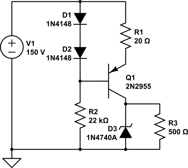
A simple low voltage/current power supply that can accept a wide range of input voltages, up to several hundred volts. The input range is specified as 20 to 160V DC, with an output requirement of 10V and a maximum...
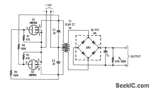
This inverter is capable of delivering high-voltage AC or DC, utilizing a rectifier and filter, with outputs reaching several hundred volts. The transformer T1 features a power rating of 12.6 to 440 V, with the primary and secondary windings...
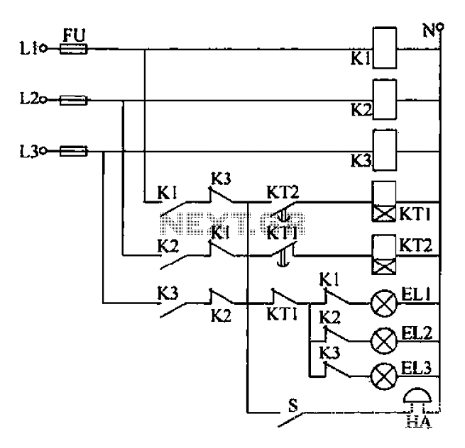
Any power supply and distribution sector should include phase sequence detection to ensure that the power supply phase sequence remains stable and unchanged. Additionally, any irreversible electromechanical product should also incorporate phase sequence detection to verify the phase sequence...
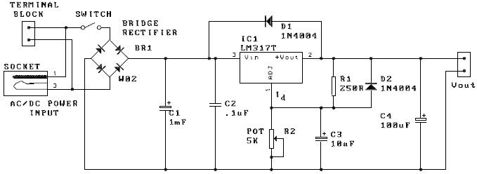
A potentiometer, designated as R2, can be utilized to adjust the desired output voltage. The kit is capable of accepting either AC or DC input through a socket or terminal block. It is advisable to incorporate protection diodes when...
The value may vary based on the switching frequency, environmental conditions, and required reliability level; therefore, it is advisable to verify this with the actual load. The maximum ambient temperature represents the highest temperature that can meet the coil...
High Current Variable Power Supply Circuit Diagram. The widely used variable voltage regulator IC LM317 can handle a maximum current of only 1 ampere, making it unsuitable for applications requiring a high current variable power supply. The design of a...