
Power phase sequence display circuit

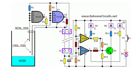
The described circuit for phase sequence detection in a three-phase power supply system is crucial for ensuring operational safety and reliability. The circuit employs a voltage rectifier (UR1) to convert the AC voltage from the power supply into DC voltage. This DC voltage is then used to charge capacitor C2 through resistors R3 and Ri. The neon bulb EL1, which indicates the correct phase sequence, is activated when the voltage across C2 reaches a specific threshold known as the ignition voltage.
The operation is cyclical; once EL1 lights up, it discharges C2, causing the voltage to drop. When the voltage falls below the threshold, EL1 turns off, allowing C2 to recharge again. This cycle continues, creating a visual indication of the correct phase sequence through a steady green light. The frequency of the flashing can be adjusted by changing the values of resistors RL and capacitors C2 and Shu, which affect the time constant of the charging and discharging process.
In contrast, if the phase sequence is reversed, the circuit is designed to activate a different neon bulb, EL2, which emits a red light to indicate an incorrect phase sequence. This dual-indicator system provides a clear visual cue for operators, enhancing safety and preventing potential damage to equipment that could arise from incorrect phase connections. The circuit is essential for any three-phase power supply system, particularly in industrial settings where the integrity of power supply phases is critical for the operation of electromechanical devices.Any power supply and distribution sector should phase sequence detection Huan Jj means to ensure stable power supply phase sequence unchanged. Any irreversible electromechanica l product itself should also have the phase sequence detection means in order to put into operation before the host power supply phase sequence is determined to meet the requirements. Three-phase power supply phase sequence indication circuit as shown when a forward phase sequence, voltage rectified by UR1 on R3, and through Ri charging C2, C2 when the voltage reaches neon EL1 Kai when the ignition voltage, EL1 lit., green.
Cz by EL1 discharge; C2 is lower than the voltage to be a certain value. EL1 off, Cz again charged, while EL1 again lit, C2 refreshing. Again and again, bright green neon EL1 constantly busy, Similarly, when the inverse when the phase sequence, only the red flashing neon EL2. Adjustment RL, C2 and Shu, G time constant, you can adjust the frequency of flashing neon.
Related Circuits
This is a simple regulated power supply circuit based on the well-known LM723 voltage regulator, which drives a transistor Q1 (2N3055). The output voltage regulation is achieved using potentiometer R1, allowing for an adjustable range from 0V to approximately...
The SE555/NE555 timer was first introduced by the Signetics Corporation around 1971. Pin connections and functions are as follows: Pin 1 (Ground) - This pin serves as the ground or common pin, representing the most negative supply potential of...
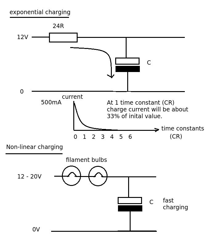
Designing a simple current limiter that charges a large 4.7mF capacitor with a charge current of approximately 500mA from a supply voltage of 10-20V. The dilemma is that there are existing MMBT2222A transistors available, which would be preferable to...
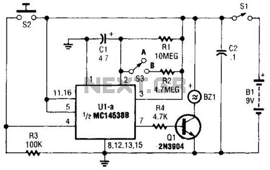
This circuit emits a loud tone if the input switch (S2) is not retriggered at designated intervals. If the user falls asleep and fails to re-trigger the circuit, it will continue to sound until S2 is pressed. The circuit operates...
This circuit is a simple air flow detector that signals the presence of air flow. The sensor utilized is a filament incandescent lamp. Components include an air flow detector, a sensor, an LED, and an LM339 operational amplifier. The air...
Simple two-wire remote monitoring unit with a three-LED level display, powered by a 9V battery. The entire project was developed at the request of a friend. The remote monitoring unit is designed to provide a straightforward solution for level indication...