
Power-switching circuit

This circuit design features a robust architecture for managing a 30 Vdc power supply, ensuring safe operation under varying load conditions. The on/off switching mechanism is initiated through command pulses, allowing for precise control over the power delivery. The integration of a 6-digit binary signal for overcurrent protection enhances the versatility of the circuit by enabling users to set specific trip points according to application requirements.
The use of a load-current-sensing resistor is critical for real-time monitoring of current flow, with the amplified voltage being directly compared to the analog voltage derived from the binary signal. This comparison is vital for maintaining the integrity of the circuit under fault conditions, as it allows for immediate response to overcurrent situations.
To improve the circuit's reliability, resistor/capacitor combinations at the inputs of the current-sensing amplifiers function as low-pass filters. This design choice effectively reduces the impact of high-frequency noise on the sensing circuit, ensuring that only significant changes in current lead to triggering the protection mechanism. The intentional delay introduced by these filters is a strategic decision to prevent nuisance tripping due to transient spikes.
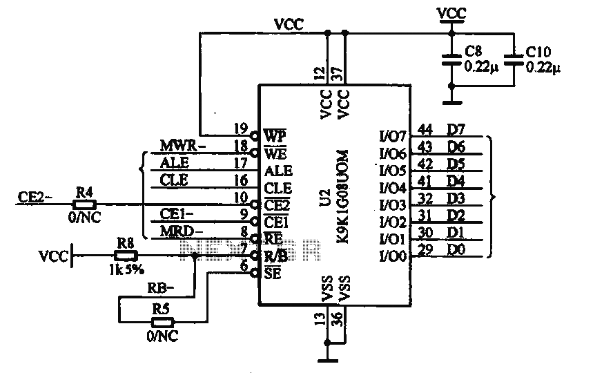
Moreover, the incorporation of 0.022 µF capacitors at the drain terminals of the PFETs is a sophisticated approach to control the switching characteristics of the power transistors. By leveraging the Miller effect, the circuit minimizes the dV/dt during turn-on, which is essential for preventing inrush currents that could otherwise damage components or lead to unstable operation.
The soft-start feature, characterized by a turn-on time of 100 to 200 ms, allows for gradual ramping of the output voltage, which is particularly beneficial in applications where sudden changes in current could adversely affect connected loads. The soft-start time is dependent on the load impedance, providing adaptability to different operational scenarios.
Overall, this circuit design exemplifies a well-thought-out approach to power management, emphasizing safety, reliability, and performance in handling a 30 Vdc power supply with load currents up to 2 A.This circuit provides on/off switching, soft starting, current monitoring, current tripping, and protection against overcurrent for a 30 Vdc power supply at normal load currents up to 2 A. The switch is turned on by an "on" command pulse; it is turned off by an "off" command pulse. An overcurrent trip can also be set on the bus side by a 6-digit binary signal, which is converted to an analog voltage and compared with the amplified voltage developed across a load-current-sensing resistor.
Resistor/capacitor combinations (0.027 µ, 2 kfi) at the inputs of the current-sensing amplifiers act as low-pass filters: this introduces a few hundred /is of delay in the response to overcurrent, thereby providing some immunity to noise. The 0.022 µ capacitors connected to the drain terminals of the PFETs provide a Miller effect, which reduces the rate of change of the drain voltage and therefore the rate of rise of current at turn-on. The soft-turn-on time depends upon the load impedance and is typically 100 to 200 ms.
Related Circuits

Logic Gates FM Transmitter Circuit Electronic Circuit Schematic Wiring Diagram. The FM transmitter circuit utilizing logic gates is a fundamental electronic design that operates by modulating a carrier frequency with an audio signal. This circuit typically consists of various logic...
This document illustrates the application of the MP3 player memory chip ACU7505 within a clamor circuit, designed to support the overall machine CPU and MP3 decoder core. The chip is utilized to address high data storage capacity requirements, implemented...
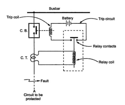
A trip unit is electrically connected in parallel with a current-limiting polymer element in series with circuit breaker contacts to function as a shunt resistance for the polymer element. It becomes energized when the polymer element transitions to its...
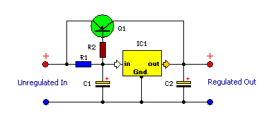
This is a compact and highly functional circuit that can be constructed on a veroboard. Voltage regulators such as the LM708 and LM317 series (among others) may occasionally require a load. The circuit utilizes voltage regulators, which are essential components...

One electronic ballast circuit is depicted in Figure 2-11. This circuit utilizes a specialized fluorescent lamp starter thyristor, SCR Y1112, which is superior to ordinary thyristors due to its ability to maintain a higher current value and dU/dt values....
Chevy S-10 Blazer Ignition Control (IC) Circuit Wiring Diagram. The Chevy S-10 Blazer ignition control circuit is a critical component in the vehicle's ignition system, responsible for managing the timing and operation of the engine's spark plugs. The circuit typically...