Fluorescent lamp electronic ballast circuit
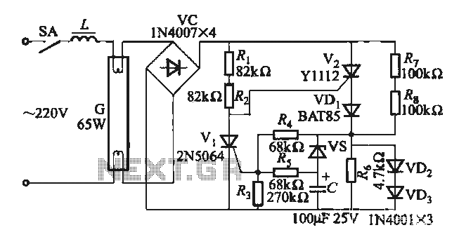
One electronic ballast circuit is depicted in Figure 2-11. This circuit utilizes a specialized fluorescent lamp starter thyristor, SCR Y1112, which is superior to ordinary thyristors due to its ability to maintain a higher current value and dU/dt values. This design ensures a flicker-free start for fluorescent lamps and contributes to a longer lifespan.
The electronic ballast circuit serves as an essential component in fluorescent lighting systems, providing the necessary voltage and current regulation to start and operate the lamps efficiently. The use of SCR Y1112 as a starter thyristor enhances the circuit's performance by allowing it to handle higher current levels, which is crucial for initiating the fluorescent lamp's ionization process.
The circuit typically includes input power connections, a control circuit that regulates the thyristor's firing angle, and output connections to the fluorescent lamp. The SCR Y1112 is strategically placed in the circuit to control the initial surge of current, preventing flicker during startup. This thyristor's high dU/dt capability minimizes the risk of voltage spikes, which can adversely affect the lamp's performance and lifespan.
Additionally, the design incorporates filtering components to smooth out any voltage fluctuations and prevent electromagnetic interference, ensuring stable operation. The electronic ballast also contributes to energy efficiency by reducing power consumption compared to traditional magnetic ballasts, making it an environmentally friendly option for lighting applications.
Overall, this electronic ballast circuit is engineered for reliability and longevity, making it suitable for various applications in commercial and residential lighting systems.One (1) Electronic Ballast circuit circuit shown in Figure 2-11. This circuit uses special fluorescent lamp starter thyristor SCR Y1112, ordinary thyristor phase than having to maintain a higher current value, dU / dt values, can ensure flicker-free fluorescent start, long life expectancy.
