
Powering Electret Microphones

To power an electret condenser microphone, the typical configuration involves connecting a resistor and a capacitor to create a suitable biasing and coupling network. In this case, a 1 kΩ resistor is employed to provide the necessary bias voltage to the microphone's internal FET (Field Effect Transistor), which is essential for the microphone to operate effectively. The resistor connects the positive terminal of the microphone to a DC voltage supply, typically between 1.5V and 9V, depending on the specific microphone specifications.
The 10 µF capacitor serves as a coupling capacitor, which allows the audio signal generated by the microphone to pass while blocking any DC voltage present at the microphone’s output. This capacitor is connected to the output terminal of the microphone, ensuring that only the AC audio signal is transmitted to the subsequent audio processing stages, such as an amplifier or audio interface. The other terminal of the microphone is grounded, which establishes a common reference point for the circuit.
It is important to ensure that the capacitor's voltage rating exceeds the supply voltage to prevent breakdown. Additionally, the values of the resistor and capacitor can be adjusted based on the desired frequency response and sensitivity of the microphone circuit. The selected values of 1 kΩ and 10 µF provide a good balance for general audio applications, allowing for effective signal transmission while maintaining stability in the circuit. Proper PCB layout practices should be followed to minimize noise pickup and ensure reliable operation of the microphone in various environments.I want to power a condenser MIC ( Electret 2 terminals ). I connected a resistance of 1k and capacitance of 10uf to its positive terminal and grounded other te.. 🔗 External reference
Related Circuits
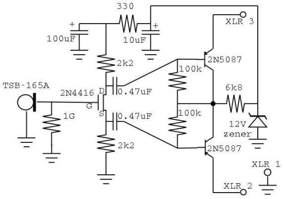
These small diaphragm condenser microphones were constructed as a project for an Electronics III class. The circuit layout and design of the microphones are inspired by DIY microphone projects by Scott Helmke (the "Alice" mic) and Stefan Avalos' small...
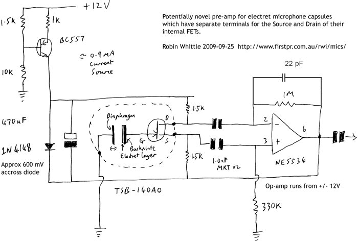
This circuit may be of interest to individuals designing preamplifiers for electret and externally polarized condenser microphones that lack an internal FET. If the noise from a single FET is a limiting factor, utilizing two or four FETs in...
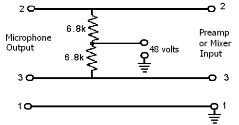
These devices require power to operate. This power can be supplied by a battery inserted into the microphone, a separate dedicated power supply with a specialized multi-pin cable, or most commonly, phantom power. Phantom power is supplied by a...
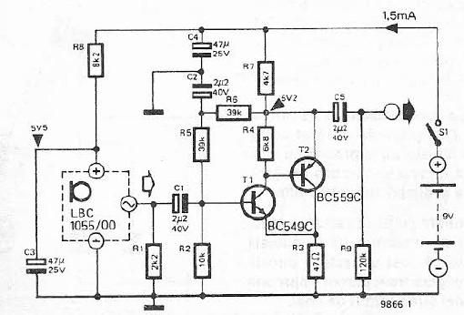
This electret microphone amplifier is constructed using standard electronic components. It is designed to work with an electret microphone capsule, although it can also accommodate a dynamic microphone that has low resistance. The circuit operates with a supply voltage...
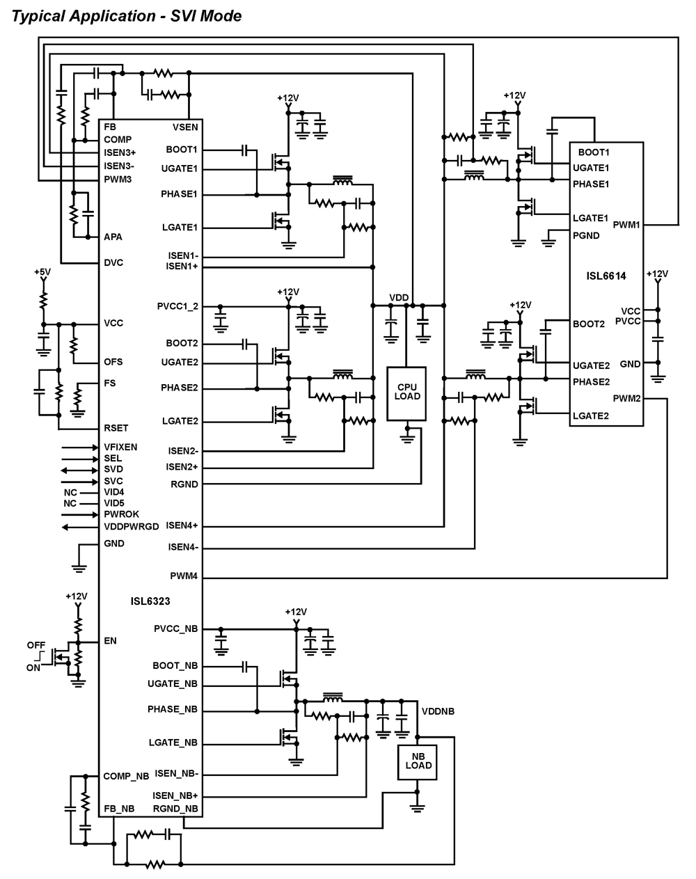
The ISL6323 dual PWM controller provides high efficiency and precise regulation through two synchronous buck DC/DC converters. It supports hybrid power control for AMD processors, operating via either a 6-bit parallel VID interface (PVI) or a serial VID interface...
This is a simple stereo electret microphone preamplifier circuit. For optimal performance, it is recommended to use solid or film capacitors and metal film resistors. The circuit is based on a single IC, the LM358. It is straightforward, cost-effective,...