
/cardioid condenser microphones

The small diaphragm condenser microphone operates by converting sound waves into electrical signals using a diaphragm that vibrates in response to sound pressure. The design typically includes a backplate that creates a capacitor with the diaphragm, allowing for the detection of minute changes in capacitance caused by sound waves. The microphones described are particularly suited for capturing high-frequency sounds and are often used in studio recording and live sound applications.
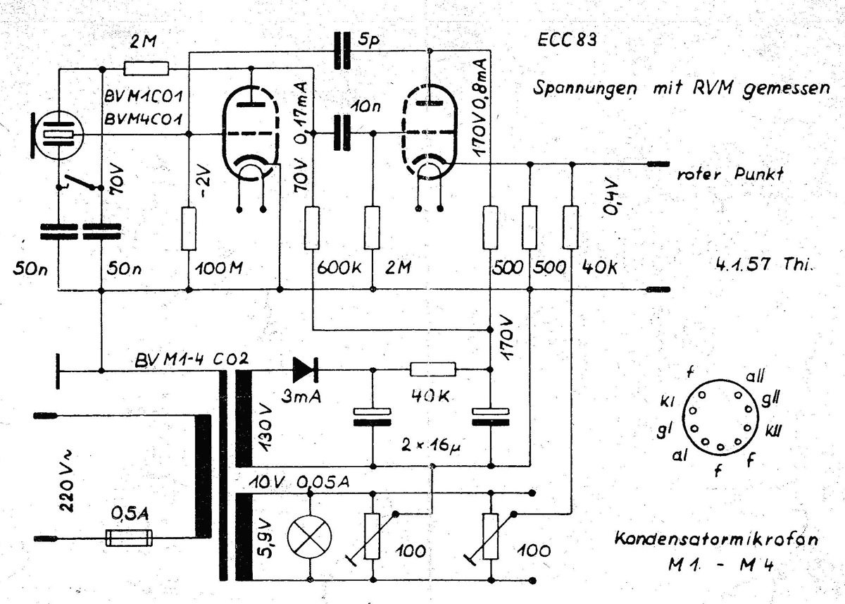
The circuit schematic referenced in this project employs a Schoeps-style design, which is known for its high fidelity and low noise characteristics. This circuit configuration requires a 48V phantom power supply, which is standard in professional audio equipment. Phantom power is supplied through the microphone cable, allowing for both power and audio signal transmission without the need for separate power lines.
Key components in the circuit include the microphone capsule, a preamplifier, and passive components such as resistors and capacitors that help shape the frequency response and impedance matching. The preamplifier is crucial as it boosts the weak signal from the microphone capsule to a level suitable for further processing or amplification. The careful selection of components and layout ensures minimal interference and optimal performance.
In summary, the construction of these small diaphragm condenser microphones involves a thoughtful integration of established designs and modern electronic principles, resulting in high-quality audio capture suitable for various applications in the field of sound engineering.I built these small diaphragm condenser mics as a project for an Electronics III class. The circuit layout and design of the microphones are based on DIY microphone projects by Scott Helmke (the ""Alice"" mic) and Stefan Avalos` small cardioids. The circuit schematic used is based off the Schoeps circuit and requires 48V of Phantom. 🔗 External reference
Related Circuits
Piezo Disks, Audio Schematics, and a Condenser Microphone. The schematics and diagrams provided serve as a foundation for sonic investigations utilizing piezo disks and microphones, along with connections to 2 and 3 terminal electret condenser stage buffers that address...
Condenser microphones generally provide superior sound quality compared to dynamic microphones. For those unfamiliar with these two microphone types, a Wikipedia article can offer useful insights. Electret condenser microphones consist of two plates (capacitors), one of which vibrates in...
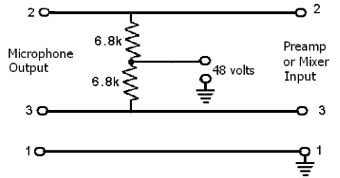
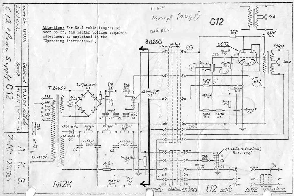
These devices require power to operate. This power can be supplied by a battery inserted into the microphone, a separate dedicated power supply with a specialized multi-pin cable, or most commonly, phantom power. Phantom power is supplied by a...
The power supply is integrated into the base of the microphone, which may cause hum issues, even with the onboard potentiometer designed to nullify this effect. Consequently, the microphone features two cables: one for power and another for audio...
One of my prize pieces of equipment is a pair of Sony C-37A large capsule tube, condenser microphones. I bought these from the radio station at college because they were getting hard to use, and an intermittent connector problem...
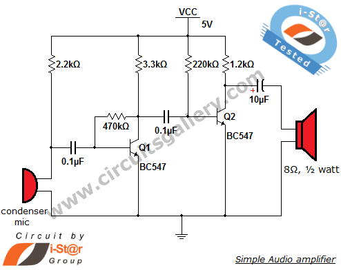
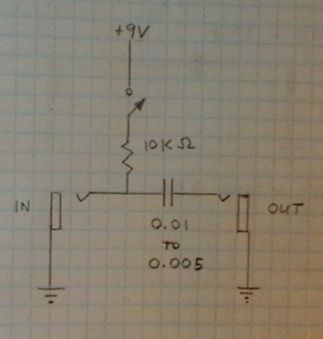
This circuit diagram is a simple and effective design for amplifying weak signals from a capacitive condenser microphone. It is suitable for sound sensing applications and various automatic robotic sensors. While a more complex audio amplifier circuit using the...