
PQS1 series magnetic disk control panning control circuit

The described system integrates a master controller with a PQS1 Series Magnetic control panel, which serves as the central unit for managing the operational parameters of the bridge crane hoist. The control circuit is meticulously designed to facilitate precise control over the lifting and lowering mechanisms of the crane.
The master controller handle SA, with its seven distinct positions, provides operators with the flexibility to select from three different lifting speeds, enhancing operational efficiency based on the load requirements. The zero position serves as a safety feature, engaging the parking brake to secure the crane when not in operation.
The three drop blocks are critical for managing the descent of the load. The second block is specifically intended for single-phase braking, allowing for controlled lowering of the load. The forced descent feature, activated by the first three blocks, ensures that the crane can safely lower heavy loads under specific conditions, thereby preventing uncontrolled descent.
The timing mechanisms, including the motor delay of 0.65 seconds and the relay KTi's pull and off delays, are essential for ensuring the safety and reliability of the system. The motor delay prevents abrupt stopping that could lead to a heavy slip of the hook, while the relay delays serve to extend the contact access time, effectively minimizing the risk of phase short circuits. These features collectively enhance the operational safety and efficiency of the bridge crane hoist, making it suitable for various industrial applications where precise load handling is crucial. By master controller and PQS1 Series Magnetic control panel consisting of a control circuit for controlling the bridge crane hoist lifting mechanism of control. Master controll er handle SA has seven positions: In addition to the zero position, there are three lifting gear, lift speed can be obtained in three different degrees; there are three drop block, the second block for the single-phase brake down first 3 block is forced down if it is the weight of the transition to a system for generating motion decline; first stop only when pulled from the first block of the first block 2, 3, in order to pull down the brake for fall, nowhere else. Zero parking brake when YA first action, the motor delay o. 65s after power to prevent stopping power generated with heavy slip hook. Commutation of the relay KTi pull delay is 0.11N0.16 s, off delay is 0.15 ~ 0. 2s, the main purpose is to extend contacts for access time, to avoid phase short circuit.
Related Circuits
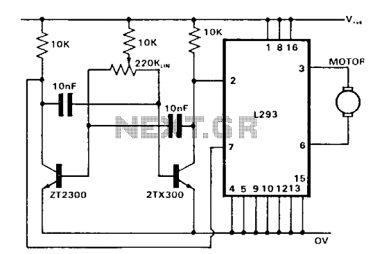
The control of both direction and proportional motor speed is accomplished through the rotation of a single potentiometer. The motor driver utilized is the SGS integrated circuit L293, which can drive up to 1 amp in either direction, depending...
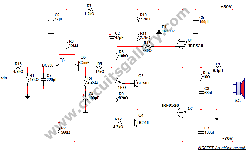
This is a MOSFET transistor-based power amplifier circuit that operates within a voltage range of +35V to -35V. The input voltage is pre-filtered and pre-amplified before being applied to the MOSFET switch. The pre-audio amplifier consists of a differential...

This Project Automatic Room Light Controller with Visitor Counter using Microcontroller is a reliable circuit that takes over the task of controlling the room lights as well as counting the number of persons/visitors in the room very accurately. When...
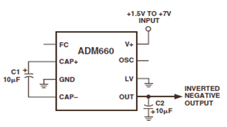
The ADM660 is a charge-pump voltage converter that can either invert the input supply voltage or double it. The schematic below depicts the ADM660 Voltage Inverter Circuit Configuration Diagram. This inverting schematic is ideal for generating a negative rail...
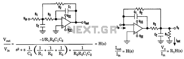
The low-pass Sallen-Key filter is a staple for designers because it contains few components. By redesigning the filter, a current-to-voltage conversion can be avoided when the input signal to be filtered is in current form. The Sallen-Key filter is a...
This circuit allows for the adjustment of a fan's speed from a distance, such as from a couch or bed. It utilizes an infrared receiver module TSOP1738 to capture the infrared signals sent by a remote control. The circuit...