
Bi-directional motor control

The described circuit employs a single potentiometer to manage both the speed and direction of a DC motor, leveraging the capabilities of the L293 motor driver IC. This integrated circuit is designed to control the direction of the motor based on the logic levels applied to its input pins. The L293 can handle a maximum current of 1 amp per channel, making it suitable for small to medium-sized motors.
The operation of the motor is dictated by the states of input 1 and input 2. When input 1 is set to a high logic level while input 2 is at a low logic level, the motor is energized to rotate in a designated forward direction. Conversely, when input 1 is low and input 2 is high, the motor reverses its direction. This dual control mechanism allows for straightforward directional control through simple logic states.
The incorporation of a variable motor speed ratio flip-flop introduces an additional layer of control over the motor's speed. This component allows for the modulation of the motor’s speed by varying the duty cycle of the input signals. The potentiometer (RV1) serves as an adjustable resistor, enabling the user to set the desired motor speed. In its neutral or center position, the motor speed ratio is set to 1:1, effectively halting the motor due to a lack of sufficient input frequency for tracking.
As the potentiometer is rotated away from the center position, the motor speed ratio is altered, resulting in a gradual increase or decrease in motor speed. The average voltage bias created by this adjustment is directly proportional to the new motor speed ratio, allowing for smooth transitions in speed control. This method of control is particularly useful in applications requiring precise speed adjustments and directional changes, providing a versatile solution for motor management in various electronic projects.The control of both direction and of proportional motor speed is achieved by rotation of a single potentiometer. The motor driver is an SGS integrated circuit L293 which will drive up to 1 amp in either direction, depending on the logic state of input 1 and input 2 as per table.
I/P 1 I/P 2 Function. High Low Motor turns one way. Low High Motor reverses. By applying a variable M/S ratio flip-flop to these inputs, both speed and direction will be controlled. With RV1 in its center position the M/S will be 1:1 whereby the motor will remain stationary due to its inability to track at the flip-flop frequency.
Movement of RV1 in either direction will gradually alter the M/S ratio and provide an average voltage bias in one direction proportional to the M/S ratio.
Related Circuits
The DTMF codec stands for dual-tone multi-frequency codec. The multiple-channel infrared remote control switch circuit that incorporates the DTMF is depicted in the figure. It consists of an infrared remote control signal emitter, an infrared receiving signal amplifier, a...
The BC547B transistor has a collector-base voltage (Vcbo) of 50V, a collector-emitter voltage (Vceo) of 45V, and an emitter-base voltage (Vebo) of 6V. In contrast, the BC548 transistor in the original circuit has a Vcbo of 30V, a Vceo...
The circuit operates by using a clock signal to drive four D-flip-flops in the control section, which store the on/off state of each current direction for the two stepper motor coils. The flip-flops create a finite state machine (FSM)...
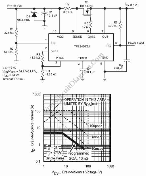
This is a positive high-voltage hot swap controller circuit with a power limiter. This circuit utilizes the TPS2491 or TPS2490, as both of them have specific features. The positive high-voltage hot swap controller circuit is designed to safely connect and...
Pulse width modulation (PWM) is a technique to control analog circuits with a digital output. PWM is used in many applications, especially to control light intensity and speed on motors. A PWM circuit makes a square wave with a...
A thermally controlled switch operates based on the surrounding temperature without human intervention, except during the construction of the electronic thermostat. This type of switch has numerous practical applications. For instance, it can activate an additional fan when the...