
Preamp Mixer Stomp-Box for Dobro Guitar

The stomp-box preamp circuit is characterized by its dual-channel architecture, enabling simultaneous use of the piezo and microphone inputs. The signal path begins with the piezo transducer connected to a low-noise gain stage, ensuring high fidelity and minimal interference. The SSM2139 amplifier provides a high input impedance, which is essential for maintaining the integrity of the piezo signal. The microphone input, equipped with phantom power, is designed to accommodate professional-grade microphones, ensuring versatility in various performance settings.
The mixer section, utilizing the OP275, allows for precise control over the individual channel levels, facilitating seamless blending of the two audio sources. The inclusion of a rotary fader for each channel enhances user control, enabling real-time adjustments during performances. The Butterworth low-pass filter effectively mitigates unwanted high-frequency noise, while the active filter centered at 1 kHz allows for tonal shaping, critical for achieving the desired sound profile of the Dobro.
The stomp switch serves a dual purpose; it not only bypasses the master volume control but also indicates the operational status of the unit, enhancing usability on stage. The independent tuner output and signal level indicator provide additional functionality, ensuring that the performer can monitor their signal levels effectively.
The robust design of the unit, including its aluminum housing and internal power supply, ensures reliability and durability for road use. The transition to a modified Fishman Pocket Blender reflects the evolving needs of the artist, highlighting the importance of adaptability in audio equipment design. This preamp system exemplifies the integration of advanced electronic components to meet the demands of professional musicians, delivering high-quality sound reinforcement while maintaining ease of use.I designed and built this stomp-box forGrammy-winning resophonic guitar player Stacy Phillips. Stacy typically uses two transducers on his Dobro-style instruments: a piezo element mounted internally and a gooseneck-mounted electret microphone positioned an inch or so above the resonator cover. When I built this preamp in 1996, his microphone cons isted ofan AudioTechnica AT831b capsule connected to anAT8530 power module. The power module could use batteries or 5-52 V phantom power, and had an XLR male output jack. A boost/cut tone control centered on 1 kHz (this is the approximate fundamental resonant frequency of the Dobro`s resonator and proves to be important for setting up the instrument`s amplified sound). A defeatable low-pass filter to eliminate a high-frequency "tink" sound, which Stacy found irritating.
We identified this sound as pick (attack transient) noise with an audible bandwidth of 12-20 kHz. Link here to a FFT output (Fast Fourier Transform) from Sound Designer II which helped us determine this (please use your browser`s "back" button to return). Compact and rugged construction suitable for portability and road use. Stacy reluctantly agreed to let the unit`s power supply use an external wall-wart transformer rather than batteries.
From my notes I have scanned the Dobro preamp`s schematic diagrams and modification records. You can see these images by clicking the links below. (You will need to use your browser`s "back" button to return. ) Circuit The unit has two independent input channels feeding an Analog Devices OP275-based mixer, with a rotary fader for each. The 1/4-inch input for the piezo transducer leads to an SSM2139-based low-noise non-inverting gain stage with a 1 M-ohm input impedance.
The XLR female microphone input, with selectable +15V phantom power, is coupled to an Analog Devices SSM2017 microphone preamplifier chip. Each preamp stage has an input gain trim control accessible by screwdriver through the unit`s cast aluminum enclosure for pre-setting the optimal signal/noise ratio.
Following the mixer is a bypassable fourth-order Butterworth low-pass filter with 24 dB of attenuation at 14 kHz. This is followed by a defeatable, variable boost/cut second-order active filter centered on 1 kHz. A heavy-duty DPDT stomp switch allows bypass of a master volume control which follows these filter stages, and also sets the status of a jumbo green LED-"on" for solo (bypass).
Signal to a tuner output buffer (with a 1/4-inch female jack) and an LED signal level indicator circuit (relative green intensity = signal level, red = near clip threshold) is independent of the volume control and stomp switch status. The audio path leading to the main balanced and line outputs passes through an Analog Devices SSM2402 analog switch, as a "pop"-less muting circuit, which is controlled by a panel switch, for muted tuning when desired; a blue LED indicates muted status.
An OP275 configured as a non-inverting unity-gain buffer drives the line-level 1/4-inch capacitor-coupled output. The low-impedance, balanced male XLR output is driven by a SSM2139-based transformerless balanced line driver circuit which is protected from house phantom power by capacitor coupling and zener diode clamps to ground.
Except for the 9 VAC wall-wart transformer, the power supply is internal and provides the preamp`s active components with highly regulated and filtered +/-15 VDC. The entire unit is housed in a compact 2. 06 x 3. 68 x 4. 68-inch (H x W x L) cast-aluminum enclosure. Stacy Phillips used this preamp system from late-1996 until mid-2003, when he switched to a modified Fishman Pocket Blender.
At that time we dispensed with the AT831b mic`s power module and let the blender handle that function. Stacy can now use a single cable for both transducers (rather than separate mic and piezo cables) and no longer fusses with the cumbersome AT8530 power module.
🔗 External reference
Related Circuits
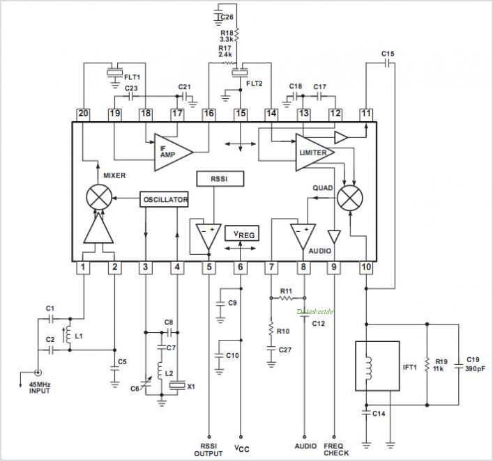
The SA608 is a low-voltage, high-performance monolithic FM intermediate frequency (IF) system that includes a mixer, oscillator, two limiting intermediate frequency amplifiers, a quadrature detector, a logarithmic received signal strength indicator (RSSI), a voltage regulator, and audio and RSSI...
This is a design for a low noise microphone preamplifier, which is ideally suited to low impedance (600 Ohm nominal) microphones. One limitation is that it is not balanced, which is not a problem in a home recording environment,...
Any electronics amateur possessing a collection of vinyl recordings and seeking high-quality reproduction should construct this preamp and integrate it into the Modular Preamplifier chain. This circuit offers a very high input overload capability, low distortion, and precise reproduction...
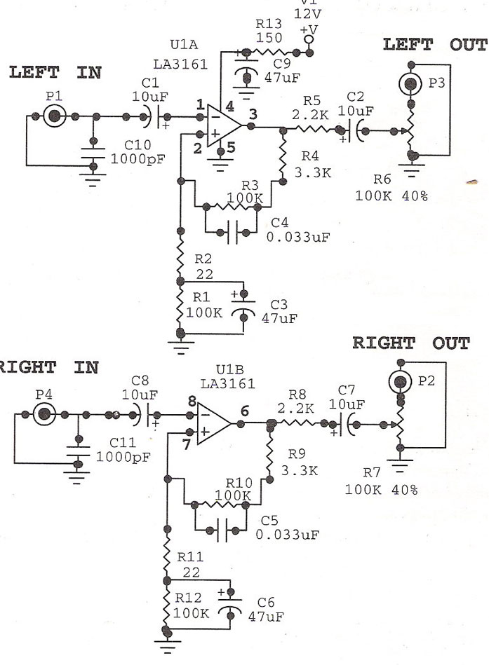
Preamplifier with LA3161. Preamplifiers are utilized to amplify low-level signals, such as those from microphones and tape heads, before they are sent to power amplifiers. The LA3161 is a versatile integrated circuit designed for use in audio preamplification applications. It...
The objective of this project was to design a small, portable mixer powered by a 9V PP3 battery while maintaining high-quality performance. The mixer consists of three main modules that can be varied in number and/or arrangement to meet...
The calculator computes the gain and output impedance of a common plate load mixer. Each input channel controls a separate grid, which affects the plate current through the common plate load resistor RL and the cathode resistor RK. The...