
4 channel portable audio mixer 18

The portable mixer circuit is structured to provide flexibility and high performance in a compact form factor. It is particularly advantageous for applications where space and power consumption are critical. The Input Amplifier Module's low-noise characteristics ensure that the audio quality remains high, even when handling sensitive signals. The variable gain feature allows users to adapt the mixer to different input levels, making it versatile for various audio sources.
The Tone Control Module enhances the audio output by allowing users to tailor the sound profile to their preferences, accommodating different musical styles or acoustic environments. The inclusion of multiple modules and the ability to rearrange them provides a customizable experience, enabling users to configure the mixer according to specific requirements.
The power efficiency of the design is noteworthy, with a total current draw of less than 6mA, making it suitable for battery-operated applications. This efficiency is achieved through careful selection of components and circuit topology, ensuring that the mixer performs well without excessive power consumption.
In summary, this portable mixer design combines functionality, flexibility, and efficiency, making it an excellent choice for musicians, sound engineers, or anyone in need of a reliable audio mixing solution in a compact package.The target of this project was the design of a small portable mixer supplied by a 9V PP3 battery, keeping high quality performance. The mixer is formed assembling three main modules that can be varied in number and/or disposition to suit everyone needs.
The three main modules are: Input Amplifier Module: a low noise circuit equipped with a variabl e voltage-gain (10 - 100) preset, primarily intended as high quality microphone input, also suitable for low-level line input. Tone Control Module: a three-band (Bass, Middle, Treble) tone control circuit providing unity-gain when its controls are set to flat frequency response.
It can be inserted after one or more Input Amplifier Modules and/or after the Main Mixer Amplifiers. The image below shows a Block diagram of the entire mixer featuring four Input Amplifier Modules followed by four in-out switchable Tone Control Modules, one stereo Line input, four mono Main Faders, one stereo dual-ganged Main Fader, four Pan-Pots, a stereo Main Mixer Amplifier Module and two further Tone Control Modules switchable in and out for each channel, inserted before the main Left and Right outputs. Obviously this layout can be rearranged at everyone wish. An astonishing feature of this design lies in the fact that a complete stereo mixer as shown below in the Block diagram draws less than 6mA current!
The basic arrangement of this circuit is derived from the old Quad magnetic pick-up cartridge module. The circuit was rearranged to cope with microphone input and a single-rail low voltage supply. This low-noise, fully symmetrical, two-transistor head amplifier layout, allows the use of a normal FET input Op-Amp as the second gain stage, even for very sensitive microphone inputs.
The voltage-gain of this amplifier can be varied by means of R9 from 10 to 100, i. e. 20 to 40dB. This is a straightforward design using the Baxandall-type active circuitry slightly modified to obtain a three-band control. Total voltage gain of this module is 1 when controls are set in their center position. The schematic of this circuit is drawn as a stereo unit to better show the input Main Fader and Pan-Pot connections.
The TL062 chip contains two TL061 op-amps into the same 8 pin case and is wired as two virtual-earth mixer amplifiers having a voltage gain of about 4, to compensate for losses introduced in the passive Pan-Pot circuitry. Therefore, total voltage-gain is 1. These parts must be wired as shown in the above circuit diagram, connecting R3 and R4 to pin #2 and pin #6 of IC1 for Right and Left channel respectively.
These IC1 pins are the "virtual-earth mixing points" and can sum together a great number of channels. To parts listed above should be added: one Main on-off SPST switch, a LED used as pilot-light with its dropping 2K2 1/4W series-resistor, DPDT switches to enable or omit Tone Control Modules as shown in the Block diagram, input and output connectors of the type preferred, one stereo dual-gang 100K potentiometer to fade the Stereo Line Input as shown in the Block diagram, battery clip, PP3 9V battery, knobs etc.
🔗 External reference
Related Circuits
An electronic project detailing a D.C. mixer for synthesizers and various control applications. The D.C. mixer circuit is designed to combine multiple direct current (DC) signals into a single output, making it particularly useful in synthesizer applications where different control...
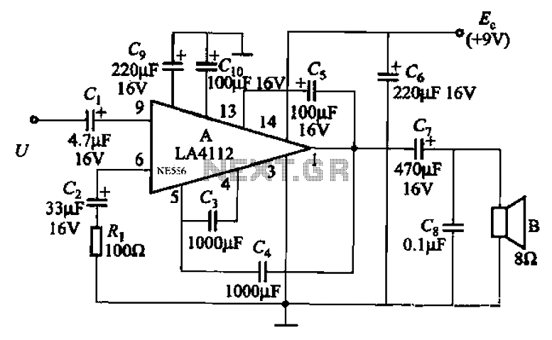
Audio power amplifier circuit utilizing the LA4112 integrated power amplifier along with additional components as shown in the figure. The audio power amplifier circuit based on the LA4112 integrated power amplifier is designed to deliver high-quality audio amplification for various...
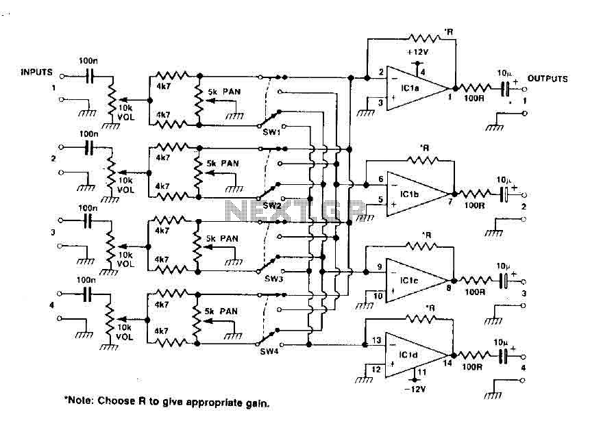
This circuit functions as a mixer for stereo tracks, utilizing a quad operational amplifier IC to provide gain for each track. The pan control allows for panning between two tracks when the switch is set to high, and when...
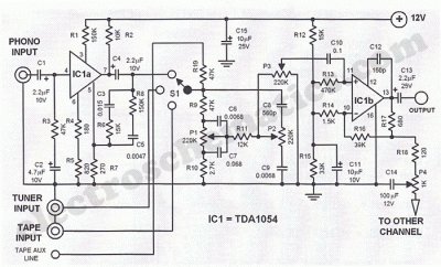
This Hi-Fi stereo preamplifier circuit is constructed using the TDA1054 integrated circuit (IC) from SGS. The TDA1054 is housed in a 16-pin DIL package and incorporates two separate preamplifier circuits. It is characterized by low noise and minimal issues...
The individual is new to electronics but enjoys experimentation. They plan to create a small guitar amplifier based on a 30 Watt design, specifically the single 12VDC version referenced in comments. The intention is to incorporate a preamplifier to...
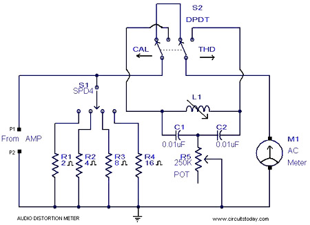
This is a simple 1 kHz audio distortion meter designed to measure the Total Harmonic Distortion (THD) on any load at any output power. The circuit allows for the selection of load impedances of 2, 4, 8, or 16...