
Band 2 Preamplifier

The described circuit employs a cascode configuration, which is beneficial for enhancing gain while maintaining stability and bandwidth. The lower 2N3819 FET, configured in common source mode, provides the initial amplification. This configuration is characterized by a high input impedance and a moderate output impedance, making it suitable for the amplification of weak signals.
The upper 2N3819 FET operates in common gate mode, which is advantageous for high-frequency applications. This configuration allows for a lower output capacitance, thereby improving the frequency response of the circuit. The common gate arrangement effectively isolates the lower stage from the load, reducing the Miller effect and enhancing overall gain performance.
Tuning capability is an essential feature of the circuit, facilitated by the adjustable lower FET. This tunability allows for the selection of a specific frequency, optimizing the circuit's performance for particular stations. The tuning mechanism can be implemented using a variable resistor or a similar component that alters the gate voltage of the lower FET, thus adjusting its operating point.
Coil details, which are crucial for determining the resonant frequency and impedance matching of the circuit, will further influence the overall performance. The choice of inductance and quality factor of the coils used in conjunction with the FETs will impact the efficiency and selectivity of the circuit. Proper attention to these components will ensure that the circuit achieves its intended high-frequency gain while maintaining stability and fidelity in signal processing.The circuit uses two 2N3819 FET`s in cascode configuration. The lower FET operates in common source mode, while the upper FET, operates in common gate, realising full high frequency gain. The bottom FET is tunable allowing a peak for a particular station. Coil details follow: 🔗 External reference
Related Circuits
Another unit of graphic EQ with five bands. The basic difference with the other circuits is that instead of an IC, a transistor is used and the power supply goes up to +/- 24V DC, ensuring low distortion and...
The provided description pertains to a graphic equalizer, a device used for selectively attenuating or boosting specific frequency bands in an acoustic spectrum. This function allows for the adaptation of musical reproduction to the acoustics of a particular space. However,...
The circuit described is a single JFET design that provides limited gain. By incorporating a source resistor bypass capacitor, the gain can be significantly enhanced, resembling a single stage of the original tube preamp used in guitar amplifiers. It...
This circuit design features a modular arrangement that enables users to select only the modules best suited to their needs, allowing for the construction of a chain ranging from one to five modules in length. For those seeking a...

The description refers to a classic three-way tone regulation circuit, which allows for the adjustment of low, mid, and high frequencies of an acoustic signal. The boost or cut can be adjusted within a range of ± 18 dB/oct. The...
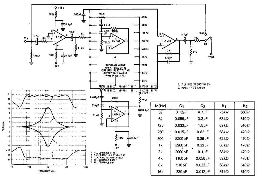
A series of active RF filters using the National LM3481C comprises a ten-band graphic equalizer. C1, C2, R1, and R2 should be at least 10% with 5% preferred tolerances. The circuit design features a ten-band graphic equalizer that utilizes a...