
PRECISION AC VOLTMETER

The circuit design leverages the properties of Zener diodes to enhance measurement accuracy significantly. The basic principle involves using a Zener diode to establish a precise reference voltage, which compensates for the inherent inaccuracies of the measuring device. In this configuration, the Zener diode is connected in reverse bias to maintain a constant voltage across its terminals, which serves as a reference point for the measurements.
The AC voltage to be measured is first rectified using a full-wave rectifier circuit, which converts the alternating current into direct current (DC). This rectified voltage is then scaled down to a suitable level for the meter using a voltage divider network. The values of the resistors in the divider are chosen based on the expected input voltage range and the desired output voltage to ensure that the meter operates within its optimal range.
The output from the voltage divider is compared to the reference voltage provided by the Zener diode. Any deviation from the reference voltage indicates a variation in the measured AC voltage. This feedback loop allows for adjustments to be made, thereby improving the overall accuracy of the measurement.
The circuit may include additional components such as capacitors for filtering noise and transient spikes, ensuring that the readings are stable and reliable. The final output can be displayed on a digital voltmeter or an analog meter, depending on the application requirements.
Overall, this circuit design not only enhances the measurement accuracy of AC voltages but also demonstrates the practical application of Zener diodes in electronic measurement systems.Measures a-c voltages between 95 and 135 v with 0. 6% accuracy while using ordinary 2% accuracy meter. Zener diodes provide reference voltage. -D. S. Belanger, Simple Circuit Increases Measurement Accuracy, Electronics, 38:22, p 69. 🔗 External reference
Related Circuits

The light-sensitive CDS cell R8 is configured in a bridge circuit with IC1 functioning as a comparator. When light strikes the CDS cell R8, the output of IC1 goes high, triggering SCR1. This action illuminates LED1 and activates opto...
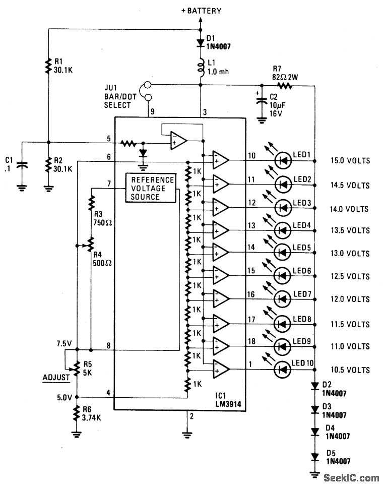
This display utilizes ten LEDs to indicate a voltage range from 10.5 to 15 volts. Each LED corresponds to a 0.5-volt increment in voltage. The main component of the circuit is the LM-3914 dot/bar display driver. A trimmer potentiometer,...
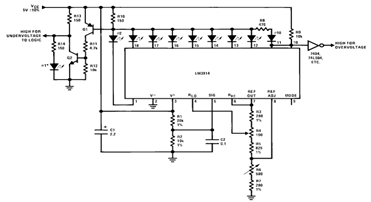
By utilizing several resistors, LEDs, and the LM3914 bar/dot display driver IC, it is possible to create a straightforward 5V voltmeter monitor circuit. This circuit offers TTL-compatible undervoltage and overvoltage warning signals. A complete circuit schematic is available below. The...
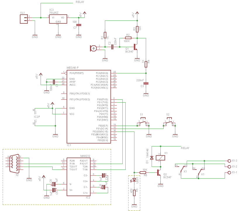
This project outlines the construction of a digital voltmeter utilizing a PIC microcontroller. A character LCD based on the HD44780 is employed to display the measured voltage. The PIC microcontroller used is the PIC16F688, which features 12 I/O pins,...
This circuit utilizes a PIC microcontroller and an internal 1 kHz sinewave table to generate an accurate sinewave. It requires only a few external components for filtering. The sinewave benefits from high frequency accuracy due to its generation from...

The primary component of this circuit is an operational amplifier (such as the 741 or 351), configured as an amplifier with a feedback circuit that consists of a diode bridge full-wave rectifier. An ammeter is connected to the rectifier...