
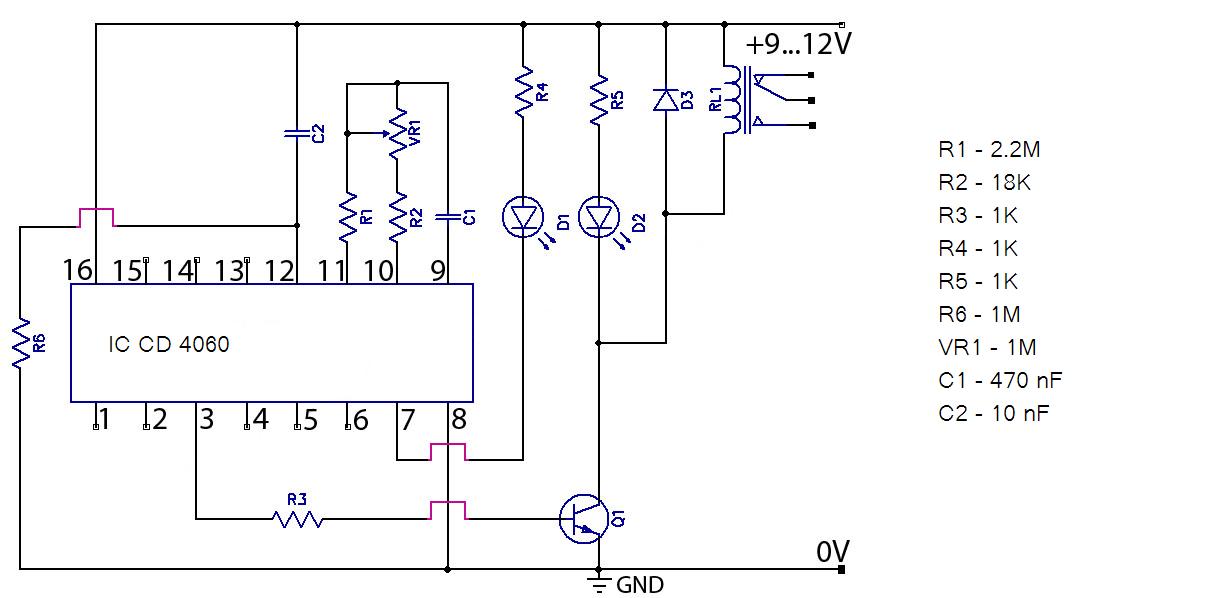
Precision Light-Activated Alarm Circuit

The circuit utilizes a light-dependent resistor (CDS cell R8) that changes its resistance based on the intensity of light it receives. In this configuration, R8 is part of a bridge circuit, which typically consists of four resistors arranged in a diamond shape. The bridge circuit is balanced under normal lighting conditions, and when light intensity changes, it causes an imbalance, resulting in a voltage difference that is detected by the comparator IC1.
IC1 compares the voltage across the bridge circuit to a reference voltage. When the light intensity exceeds a certain threshold, the voltage at one of the bridge's nodes rises above the reference level, causing the output of IC1 to transition to a high state. This output signal is then used to trigger SCR1 (Silicon Controlled Rectifier), which is a type of thyristor that can control high power loads.
Upon triggering, SCR1 allows current to flow through its anode to cathode, effectively activating the connected load. In this circuit, the load activation is indicated by the illumination of LED1, which serves as a visual indicator of the system's operation. Additionally, the activation of SCR1 also energizes opto isolator IC2. The opto isolator is crucial for providing electrical isolation between the control circuit and the load circuit, ensuring that the low voltage control side does not interfere with the high voltage load side. This design enhances safety and protects sensitive components from potential damage due to high voltage spikes.
Overall, this circuit effectively demonstrates a light-sensing mechanism that can control electrical loads based on ambient light levels, utilizing a combination of analog components and semiconductor devices for efficient operation. The light-sensitive CDS cell R8 configured in a bridge circuit with IC1 as a comparator causes ICl`s output to go high when light strikes the CDS cell R8, triggering SCR1. This lights LED1 and turns on opto isolator IC2, which switches the load.
Related Circuits
Hello everyone, please examine this circuit. I constructed it recently, but it is not functioning. I have verified all connections and components, and everything appears to be in order. However, when I power it on... The circuit in question appears...

Many applications require low-frequency signal generators that can deliver high-performance, high-resolution signals. This design idea presents a circuit that generates frequencies from 0 to 1 MHz, providing sinusoidal, triangular, and square-wave outputs with frequency resolution better than 0. A...

The project demonstration has been successfully completed, with the only remaining task being the final project report due on June 15, which will be integrated with a conference paper. This update marks the last entry in the electronic notebook,...
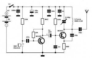
Simple FM Transmitter Circuit This simple FM transmitter circuit was built using a transistor with a transmission distance of about 300m around your home. The simple FM transmitter circuit utilizes a transistor to modulate audio signals onto a radio frequency...
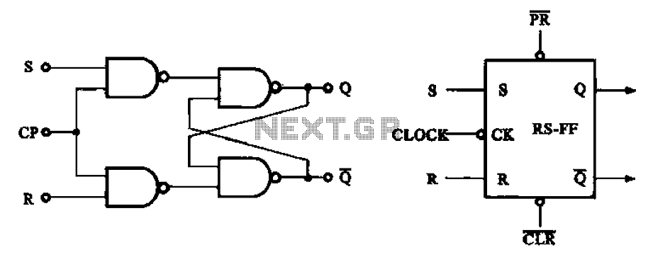
The asynchronous RS flip-flop mentioned earlier is not synchronized with the system clock signal. In contrast, the synchronous RS flip-flop incorporates synchronization, allowing it to operate in conjunction with the clock signal. Figure (a) illustrates the circuit configuration of...
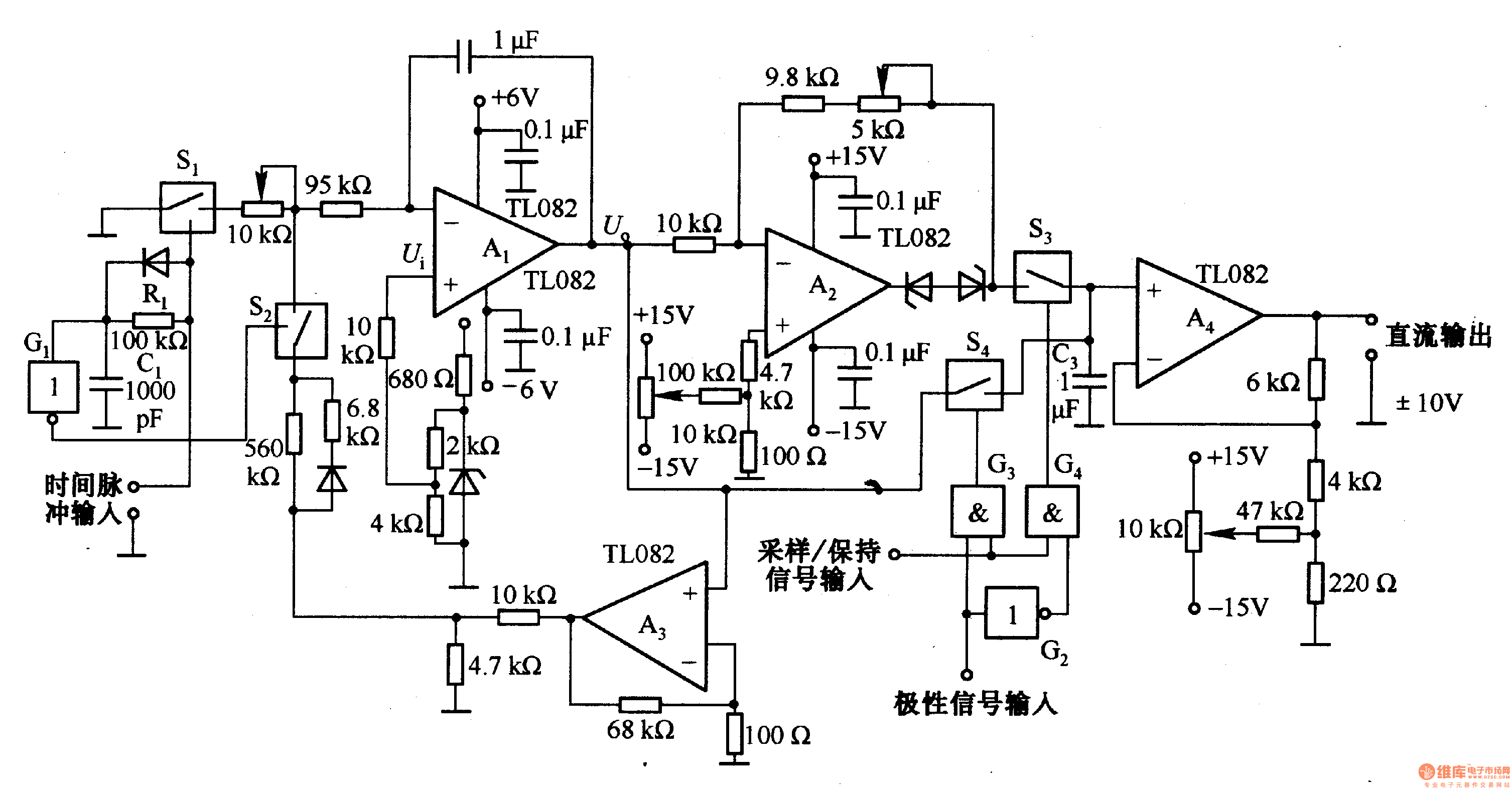
This circuit is designed for pulse width (time) to voltage conversion. According to the component parameters in the diagram, it can convert a pulse width of 0.1 seconds into an output voltage of 10V. When a conversion pulse is...