
Precision peakvoltage detector

The described circuit functions as a peak detector, utilizing an operational amplifier (op amp) in conjunction with a diode and a capacitor to capture and hold the maximum voltage level of a positive input signal. The operational amplifier is configured in a feedback arrangement that only activates during positive signal conditions, ensuring that the circuit remains responsive to peak positive voltages while ignoring negative inputs.
In this configuration, diode D1 plays a crucial role by allowing current to flow into the capacitor C when the input signal is positive. As the op amp amplifies the input signal, the inverting input is driven to the same potential as the non-inverting input, leading to the charging of capacitor C. The capacitor effectively stores the peak voltage, allowing the circuit to "remember" this value.
Upon the input signal transitioning to a negative voltage, diode D1 becomes reverse biased, preventing any discharge path through the diode. The voltage across capacitor C is maintained, but it will gradually decrease due to the op amp's input bias current, which is a very small leakage current of 10 picoamps. The discharge rate of the capacitor is primarily determined by the resistor R connected in parallel with the capacitor. The time constant, defined by the product of the resistance (R) and the capacitance (C), is set to 10 seconds, indicating how quickly the capacitor will discharge to approximately 63% of its stored voltage after the input signal drops.
This design enables the circuit to effectively track the peak voltage of a positive signal over time, making it suitable for applications where peak detection is essential, such as audio signal processing, analog-to-digital conversion, and various signal conditioning tasks. The combination of the op amp, diode, capacitor, and resistor forms a robust peak detection mechanism that can maintain the peak voltage for a significant duration, allowing for accurate monitoring and analysis of fluctuating signals.The circuit has negative feedback only for positive signals. The inverting input can only get some feedback when diode Dl is forward biased and only occurs when the input is positive. With a positive input signal, the output of the op amp rises until the inverting input signal reaches the same potential.
In so doing, the capacitor C is also charged to this potential When the input goes negative, the diode Dl becomes reverse biased, the voltage on the capacitor remains, being slowly discharged by the op amp input bias current of 10 pico amps. Thus the discharge of the capacitor is domin-antly controlled by the resistor R, giving a time constant of 10 seconds.
Thus, the circuit detects the most positive peak voltage and remembers it.
Related Circuits
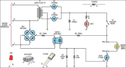
This alarm circuit was designed to monitor a mains-powered smoke detector located in a shed used for dog kennels. It provides complete isolation from the mains, allowing low-voltage (12V) cabling to be run to the alarm circuit located inside...
A circuit designed to extract and measure the modulated carrier signal from an infrared (IR) remote control. This circuit does not physically separate control pulses from modulation; instead, it amplifies the complete received signal, allowing the waveform to be...
The circuit depicted is designed to protect a system from power supplies that may exceed safe limits. An example of this is small consumer products that utilize external AC adapters, where there is a risk of accidentally connecting the...
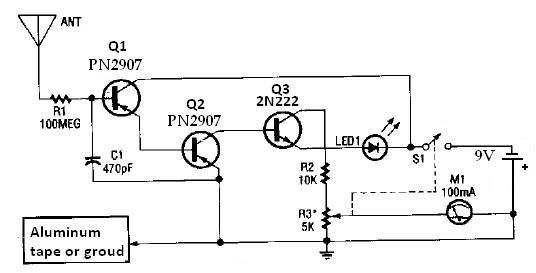
This ion detector circuit is designed to sense static charges and free ions present in the air. It is capable of detecting the presence of free ions, static electricity, or high voltage leakage. The project utilizes a short whip...
This circuit serves as an alternative to the infrared (IR) beam break detector featured in the June 2009 issue of Silicon Chip. To enhance its insensitivity to ambient light, it employs a standard IR receiver integrated circuit (IC), such...
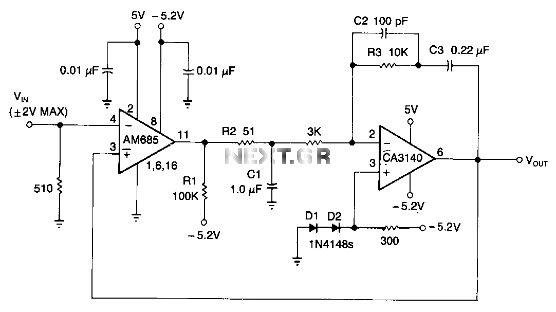
This circuit is capable of detecting positive peaks for signal frequencies exceeding 5 MHz, achieving an accuracy of ±1% for signal amplitudes ranging from 400 mV to 4 V peak-to-peak across sine, square, and triangular waveforms. The AM685 comparator...