Remote Alarm For Smoke Detector
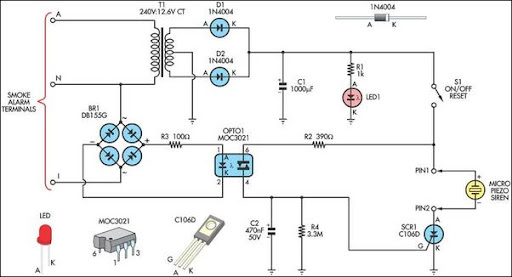
This alarm circuit was designed to monitor a mains-powered smoke detector located in a shed used for dog kennels. It provides complete isolation from the mains, allowing low-voltage (12V) cabling to be run to the alarm circuit located inside the house. In operation, the alarm signal from the smoke detector is rectified using bridge rectifier BR1 and then fed to opto-isolator OPTO1 via resistor R3. This, in turn, drives the gate of SCR1, which activates a piezo siren with an inbuilt oscillator. Power for the circuit is derived from mains transformer T1, which drives a full-wave rectifier based on diodes D1 and D2 to produce approximately 9V DC, applied to the alarm circuit via switch S1. Capacitor C1 filters the supply rail, while LED1 provides power-on indication. When the alarm is triggered, it latches on until reset by S1, requiring the switch to be opened and then closed again. A relay could be connected between pins 1 and 2 to switch larger loads than the piezo siren, such as turning on emergency lights.
The alarm circuit operates effectively by isolating the low-voltage components from the mains supply, ensuring safety while monitoring a critical area. The use of a bridge rectifier (BR1) allows for the conversion of the AC signal from the smoke detector into a DC signal, which is necessary for subsequent processing. The opto-isolator (OPTO1) serves to electrically isolate the smoke detector's output from the control circuitry, preventing any high-voltage spikes from affecting the sensitive components downstream.
The SCR1 is pivotal in controlling the piezo siren, as it provides a latching mechanism that keeps the siren activated until a manual reset occurs. This feature is crucial for alarm systems, ensuring that alerts are not inadvertently silenced without proper acknowledgment. The power supply section, comprising the transformer (T1) and the full-wave rectifier (D1 and D2), ensures that the circuit operates reliably on a stable voltage of approximately 9V DC, which is further smoothed by capacitor C1 to prevent fluctuations that could lead to false alarms or circuit malfunctions.
LED1 serves as a visual indicator of the circuit's operational status, allowing users to quickly ascertain whether the system is powered and functioning correctly. The inclusion of a relay option provides flexibility for extending the alarm system's capabilities, enabling it to control additional devices such as emergency lighting, which can be essential in alerting individuals during an emergency situation.
Overall, this alarm circuit design exemplifies a robust approach to integrating low-voltage alarm systems with mains-powered devices, ensuring both safety and functionality in monitoring environments such as dog kennels.This alarm circuit was designed to monitor a mains-powered smoke detector located in a shed (which is used to house dog kennels). It provides complete isolation from the mains so that low-voltage (12V) cabling could be run to the alarm circuit which is located inside the house.
In operation, the alarm signal (I) from the smoke detector is rectifie d using bridge rectifier BR1 and then fed to optoiso lator OPTO1 via resistor R3. This in turn drives the gate of SCR1 which turns on and activates a piezo siren with inbuilt oscillator. Power for the circuit is derived via mains transformer T1. This drives a full-wave rectifier based on diodes D1 & D2 to produce around 9V DC and this is then applied to the alarm cir cuit via switch S1.
Capacitor C1 filters the supply rail, while LED1 provides power-on indication. When the alarm is triggered, it latches on until reset by S1 (ie, the switch must be opened and then closed again). Finally, a relay could be connected between pins 1 & 2 to switch larger loads than the piezo siren - eg, to turn emergency lights on.
🔗 External reference

