
Fluid level meter version 2

IC4 functions as a critical counter and oscillator combination within the circuit architecture, facilitating the generation of an alternating current (AC) signal essential for subsequent processing. The oscillator's output, available at pin 7, is integral to the operation of the system. The AC signal is modified by a voltage divider network comprising resistors R3 and R4, which attenuates the signal before it is fed into pin 3 of IC5, a multiplexer that selectively routes the signal to various electrodes.
Simultaneously, the AC signal is also directed to a rectifier/demodulator circuit, which consists of diode D1 and resistors R1 and R5. This configuration converts the AC signal into a direct current (DC) voltage that can be analyzed for variations. The rectified signal is then compared against a stable reference voltage using IC2, which operates as a comparator in this scenario.
The operational dynamics of this system become particularly relevant when an electrode is submerged in water. The introduction of water creates an additional capacitive load on the AC signal, leading to a measurable decrease in the output voltage from the demodulator. This reduction is detected by the comparator, which subsequently alters its output level in response to the change. The rapid response of the system is facilitated by the multiplexer, which is designed to connect the AC signal to one electrode at a time, ensuring that the circuit can effectively monitor multiple electrodes in quick succession. This design allows for efficient and accurate detection of changes in the environment around the electrodes, particularly in applications involving liquid detection.IC4 is a counter/oscillator combination and is the key element in the circuit. The oscillator outputs its AC signal on pin 7. This signal is lead (through voltage divider R3/R4) to pin 3 of IC5 (multiplexer IC) which is used as an input. The same signal is also lead to the rectifier/demodulator build up with D1/R1/R5. The resulting rectified signal is compared (with IC2, an opamp) with a constant voltage. If a selected electrode is under water, there will be an extra load on the AC signal, which causes the output of the demodulator to drop a little bit.
The comparator will react by changing its output level. All this takes a fraction of a second because the multiplexer will only handle one electrode at a time by connecting the AC signal to the selected electrode. 🔗 External reference
Related Circuits
A circuit design has been conceptualized, and an Assembly code program has been drafted for a three-level mini system. The described circuit design focuses on a three-level mini system, which can be interpreted as a hierarchical structure where each level...
A few years ago, a diode-sensor based RF power meter was built using a 68HC11 microprocessor. Prior to that, an analog RF power meter with a thermal power sensor was developed. The datasheets for logarithmic amplifiers, which promised a...
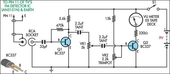
This circuit was designed to assist in the installation of TV antennas. The signal is monitored using a small portable TV set, and this circuit monitors the output of the TV's FM detector IC via a shielded lead. To...
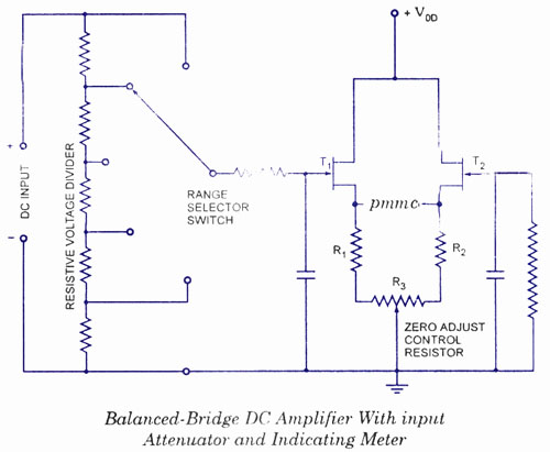
The electronic multimeter is a versatile general-purpose instrument capable of measuring both DC and AC voltages, as well as current and resistance. This solid-state device typically includes a built-in power supply for operation on AC mains and often features...
This sound level measuring device circuit can be used to control the intensity of a sound recording in the field of a disco. It has five measurement ranges between 70 and 120 dB, with a measurement accuracy of 0.5...
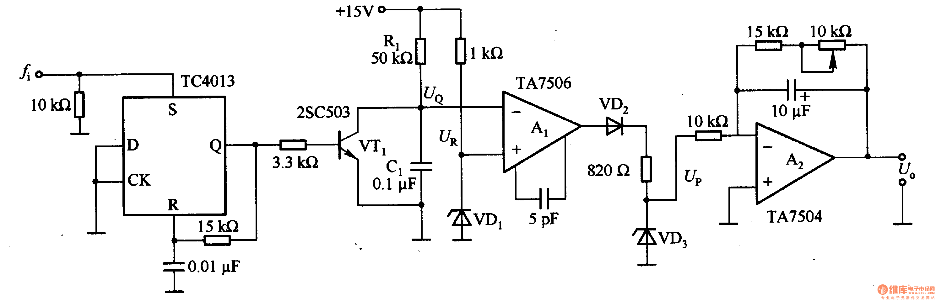
This circuit can convert an input frequency ranging from 0 to 100 Hz into an output voltage of 0 to 10 V. It utilizes the TC4013 monostable multivibrator to shape and amplify the input pulse, which has a width...