
Precision voltage controlled oscillator

The utilization of an operational amplifier (op-amp) in electronic circuits is a common practice to improve the linearity of input-output relationships. In this context, the op-amp functions as a key component to ensure that the output frequency is a linear function of the input sweep voltage.
An op-amp can be configured in various ways to achieve this linearity, including inverting, non-inverting, or differential configurations. In applications where precise frequency control is required, the op-amp can be integrated into a feedback loop to stabilize the gain and minimize distortion.
For instance, in a non-inverting configuration, the input voltage is applied to the non-inverting terminal, while the inverting terminal is connected to a resistor network that sets the gain. This configuration allows the output frequency to respond linearly to changes in the input voltage, making it ideal for applications such as signal processing, waveform generation, and frequency modulation.
Additionally, the bandwidth and slew rate of the op-amp are critical parameters that influence the performance of the circuit. A high bandwidth ensures that the op-amp can accurately follow rapid changes in the input voltage, while a high slew rate prevents distortion during fast transitions.
To further enhance linearity, external components such as capacitors and inductors may be included in the circuit design. These components can help filter out noise and stabilize the frequency response, contributing to an overall improvement in the linearity of the system.
In summary, by employing an operational amplifier, the linearity between input sweep voltage and output frequency can be significantly improved, enabling more accurate and reliable electronic circuit performance.The linearity of input sweep voltage versus output frequency is significantly improved by using an op amp.
Related Circuits
This document serves as a compilation of design notes, providing practical details as construction progresses, along with some photographs that will be included in due course. Currently, it functions as a progress report, blending immediate plans with actual construction,...
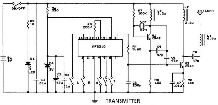
This circuit resembles that of a car radio-controlled toy with seven control functions: forward, forward-left, forward-right, backward, backward-left, backward-right, and stop. Additionally, this radio frequency circuit can be utilized for other electronic circuits that require a simple wireless motor...
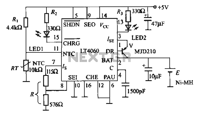
The charging circuit is designed for rechargeable batteries, particularly for situations where high charging currents can lead to increased temperatures. The LTC4060 includes an external thermistor that detects the charging temperature to prevent overheating. This device operates as a...
If a page name is not selected by pressing the button, the previously selected page name continues to be used. The value is stored in EEPROM and may be changed at any time. When the unit is first powered...
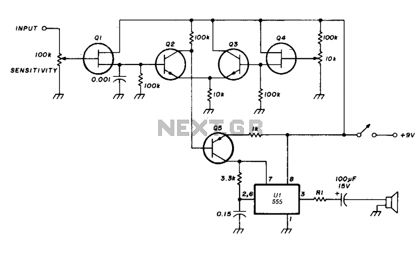
The transistor Q5 and the 1000-ohm resistor form the variable element necessary for controlling the frequency of the voltage-controlled oscillator (VCO) by limiting the charging current flowing into the 0.15 microfarad timing capacitor based on the forward bias applied...
Incandescent lamp has been used to reduce harmonic distortion in sine oscillator circuit. The nonlinear resistance characteristic of the lamp filament help the circuit to shape the signal to approximate the ideal sine wave. Here is the classic Wien-bridge...