
PREFERRED LOW LEVEL COMMON PLATE MIXER

The circuit described involves the integration of video signals with pulse signals, a process that necessitates the inversion of the input signal to ensure proper synchronization and signal integrity. The choice of resistor values is critical for defining the behavior of the circuit. For the 5670 model, R4 is set to 270 ohms, while for the 6021 model, it is adjusted to 470 ohms. This variation in resistance values likely caters to the differing electrical characteristics or operational requirements of each model.
Resistor R2, which is responsible for setting the input impedance and influencing the gain of the circuit, is specified as 680 ohms for the 5670 and 1 k ohm for the 6021. The selection of these resistor values should be aligned with the expected signal levels and the overall design goals of the circuit.
It is imperative that the input signals are maintained as positive to ensure proper operation of the circuit. The design adheres to guidelines provided in the "Handbook Preferred Circuits Navy Aeronautical Electronic Equipment," which serves as a reference for best practices in circuit design specific to aeronautical applications. This handbook emphasizes the importance of understanding the electrical parameters and operational contexts when designing circuits that integrate video and pulse signals.
Overall, the schematic design must ensure that the components are correctly rated and that the circuit functions reliably under the specified conditions. Proper attention to the values of R2 and R4, along with the requirement for positive input signals, will result in a robust electronic design suitable for its intended application.Combining of video signals with pulses is accompanied by inversion of input signal. Value of R4 is 270 ohms for 5670 and 470 ohms for 6021. R2 is 680 ohms for 5670 and 1 K for 6021. Input signals must be positive. -NBS, "Handbook Preferred Circuits Navy Aeronautical Electronic Equipment, " Vol. I, Electron Tube Circuits, 1963, PC 24, p 24-2. 🔗 External reference
Related Circuits
The only drawback of a single operational amplifier (op-amp) stage is that it inverts the signal, necessitating an additional inverting buffer to restore the original phase if absolute phase is a concern. Various schematics exist for both configurations, but...
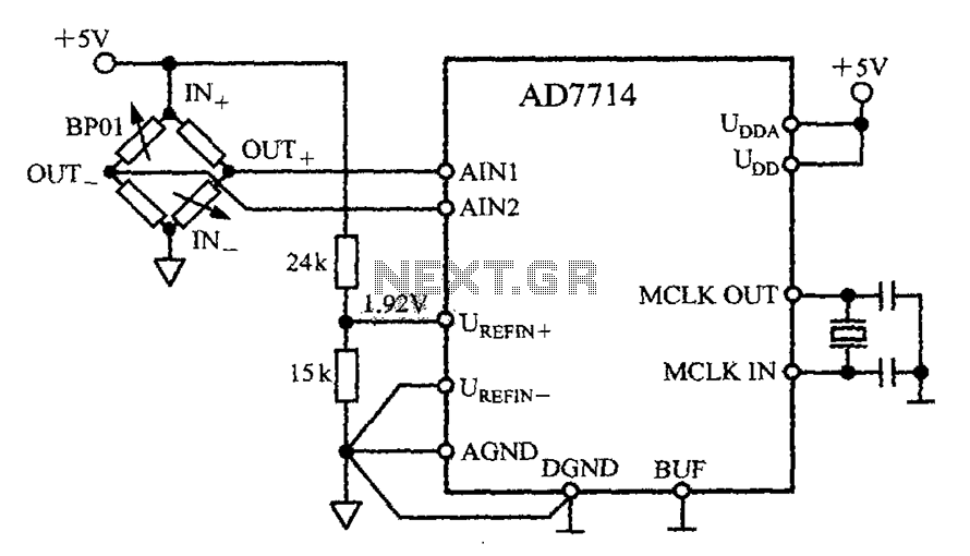
The AD7714 circuit consists of a pressure measurement system featuring the BP01 pressure sensor from Sensym. The BP01 is integrated into a bridge circuit, which produces a differential output voltage. When the sensor is subjected to its rated full-scale...

This circuit utilizes a single junction component, either one LM393 dual comparator or one LM339 quad comparator. Resistors RV1 and RV3 are responsible for establishing the full-scale reference voltage, while resistors RV2 and RV4 are used to set the...
This circuit is beneficial for liquid level detection and proximity sensing, with a range of up to 50 cm. It also features optional relay operation. The circuit operates on the principle of capacitive sensing or ultrasonic distance measurement, allowing it...
7-Segment Common LED UV Exposure Box Circuit Diagram. Features: Utilizes Stan Ocker's circuit design, employing a PIC16F84 microcontroller to count and display the time. The 7-Segment Common LED UV Exposure Box Circuit is designed for applications requiring precise timing and...
The designer requires a 1-Wire host computer IO framework that operates at 1.8V. Most 1-Wire devices are unable to function at this voltage. This application recommends implementing a 1.8V 1-Wire host computer alongside a 5V 1-Wire reference design for...