
7Segment Common LED UV Exposure Box

The 7-Segment Common LED UV Exposure Box Circuit is designed for applications requiring precise timing and display functionalities, particularly in UV exposure processes. The core of the circuit is the PIC16F84 microcontroller, which is programmed to manage the timing operations and control the display of the 7-segment LEDs.
The circuit typically consists of the following components: a PIC16F84 microcontroller, a set of 7-segment displays, resistors, capacitors, and a power supply. The microcontroller is responsible for counting the elapsed time during the exposure process. It can be programmed to start counting when the UV light is activated and to stop once the desired exposure time is reached.
The 7-segment displays are connected to the microcontroller through a series of output pins. Each segment of the display is driven by a specific pin on the PIC16F84, allowing for the representation of numerical values from 0 to 9. Additional logic may be integrated to handle transitions between tens and units, ensuring that the display accurately reflects the total elapsed time.
Resistors are used to limit the current flowing through the LEDs of the 7-segment displays, preventing damage and ensuring longevity. Capacitors may be included in the circuit to stabilize the power supply and filter out noise, which can be crucial for maintaining accurate timing.
In summary, the 7-Segment Common LED UV Exposure Box Circuit is a practical implementation of timing and display technology, effectively utilizing the capabilities of the PIC16F84 microcontroller to manage UV exposure processes accurately. This design can be adapted for various applications in fields such as photography, material science, and electronics, where controlled exposure to UV light is essential.Description: 7Segment Common LED UV Exposure Box Circuit Diagram. Features: used Stan Ocker`s circuit, uses a PIC16F84 to count and display the time .. 🔗 External reference
Related Circuits

An infrared-sensitive phototransistor is employed to detect the temperature of a soldering iron. The phototransistor must be positioned to view the tip through an opaque tube to prevent interference from stray light, and it is advisable to equip the...
This circuit utilizes a JFET to receive signals from an LED and buffer them. The output voltage is managed using an IC 1458 or LM1458, which provides approximately 7 volts in darkness and experiences a drop of about 2...

This is a versatile Low-Frequency Oscillator (LFO) designed for various modulation applications. The frequency of the LFO can be controlled by voltage, enhancing the range of sound possibilities. The pulse width of the rectangular wave can be adjusted between...

The circuit diagram illustrates a super bright LED night lamp that operates from the mains supply. A bridge rectifier (D1) is employed to convert the AC mains voltage into DC. The combination of capacitor (C1) and resistor (R1) forms...

The circuit schematics operate at 12 Volts, sourced from a car battery. The ground connection is tied to the car chassis, while the signal is received from a sensor connected to a stepper motor. The No. 5 pin of...
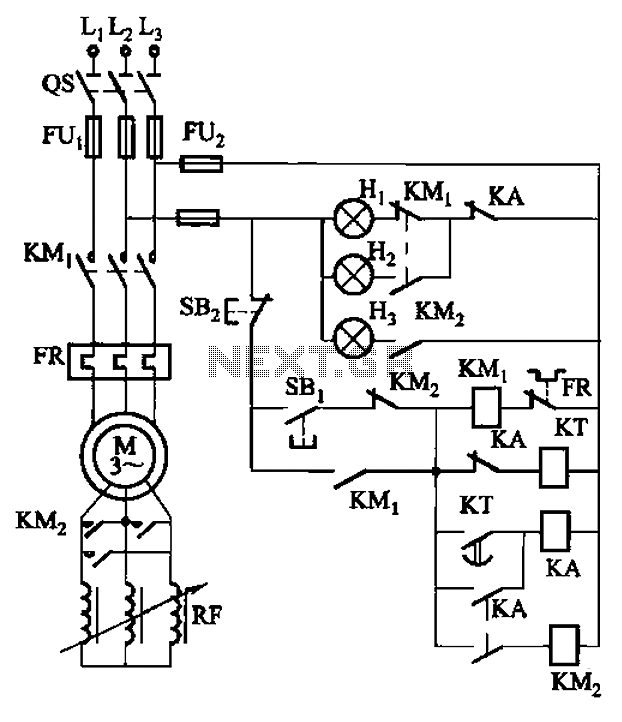
The circuit depicted in Figure 3-165 utilizes a time relay (KT) for controlling the start-up time. Indicator light Hi serves as the power indicator, H2 is designated for the start lights, and H3 functions as the running lights. The circuit...