
Programmable-attenuator

This circuit functions to divide the input signal by a chosen constant (1, 2, 4, 8, etc.). Although T, Z, or L sections could be utilized in the input attenuator, this is unnecessary since the amplifier loading is minimal, and a constant input impedance is preserved. Consequently, the circuit is simpler and more accurate than the conventional method of creating a constant impedance ladder and employing analog switches to switch sections in and out. Additionally, two identical circuits can be employed to attenuate a balanced line.
The described circuit serves as a signal divider that can be configured to reduce the amplitude of an input signal by specific factors. This functionality is particularly useful in applications where signal levels must be adjusted to prevent distortion or to match the input requirements of subsequent stages in a signal processing chain.
The circuit architecture can be based on resistive dividers, where the division ratio is determined by the resistor values selected. By using precision resistors, the circuit can achieve high accuracy in the division process. The absence of complex switching mechanisms and additional components simplifies the design, reducing potential points of failure and improving reliability.
In terms of implementation, the circuit can be designed to maintain a constant input impedance, which is critical for preventing reflections and ensuring signal integrity, especially in high-frequency applications. The minimal loading effect of the amplifier allows for direct interfacing with various signal sources without significant alteration of the signal characteristics.
For balanced line applications, the use of two identical circuits ensures that both the positive and negative phases of the signal are equally attenuated, preserving the differential nature of the signal and minimizing common-mode noise. This is essential in professional audio and communication systems, where signal fidelity is paramount.
In summary, this circuit design offers a straightforward and effective solution for signal attenuation, with the added benefits of simplicity, accuracy, and the ability to handle balanced lines efficiently.This circuit performs the function of dividing the input signal by a selected constant (1, 2, 4, 8, etc.). While T, Z, or L sections could be used in the input attenuator, this is not necessary since the amplifier loading is negligible and a constant input impedance is maintained.
The circuit is thus much simpler and more accurate than the usual method of constructing a constant impedance ladder, and switching sections in and out with analog switches. Two identical circuits can be used to attenuate a balanced line.
Related Circuits
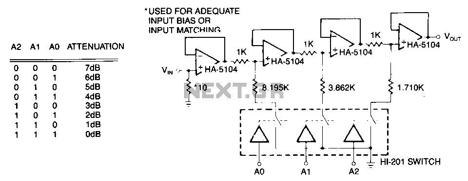
The first stage is a simple buffer used to isolate the signal source from the following attenuator stages. Each subsequent stage is preceded by a voltage divider formed by two resistors and a CMOS switch. When the CMOS switch...