
Programmable multi-tone telephone ringer

The circuit utilizes two BST72 transistors configured to amplify signals, resulting in an output voltage swing that closely matches the voltage at capacitor C3. This configuration is advantageous for applications requiring precise voltage regulation or signal amplification.
In this setup, the transistors serve as the primary amplification elements, with their collector-emitter paths connected in such a way that enhances the output voltage. The choice of the BST72 transistors is critical due to their favorable characteristics, such as high gain and fast switching capabilities, which contribute to the overall performance of the circuit.
Pins IS1 and IS2 are noted to be inoperative when the DM signal is HIGH. This indicates that the circuit has a built-in mechanism for disabling certain functions or components based on the state of the DM signal, which can be used to manage power consumption or signal routing within the circuit. The design may include additional logic to ensure that these pins are only activated under specific conditions, thereby optimizing the circuit's operation.
Volume control is facilitated by the inclusion of resistor Rv. This resistor allows for adjustable attenuation of the output signal, providing a means to control the volume in audio applications or to modulate signal strength in other contexts. The value of Rv can be selected based on the desired range of volume control, and it may be part of a potentiometer arrangement for variable adjustment.
Overall, this circuit design effectively combines transistor amplification, signal management, and user-adjustable volume control, making it suitable for various electronic applications where signal integrity and user interaction are essential.Two BST72 transistors provide an output voltage swing almost equal to the voltage at C3. Pins IS1 and IS2 are inoperative because DM = HIGH. Volume control is possible using resistor Rv.
Related Circuits
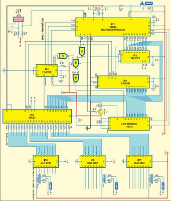
This project is based on the Atmel AT89C52 microcontroller and the Dallas real-time clock (RTC) chip DS12887. It can control and remotely program the switching operations of 24 electrically operated devices, allowing them to be turned on or off...
The given circuit, when connected in parallel to a telephone, displays the number dialled from the telephone set using the DTMF mode. This circuit can also show the number dialled from the phone of the called party. This is...
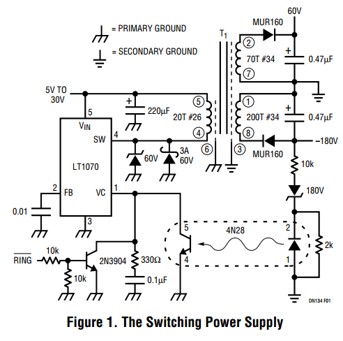
Here is a design that you can own, tailor to your specific needs, layout on your circuit board and put on your bill of materials. Finally, you will be in control of the black magic (and high voltages) of...
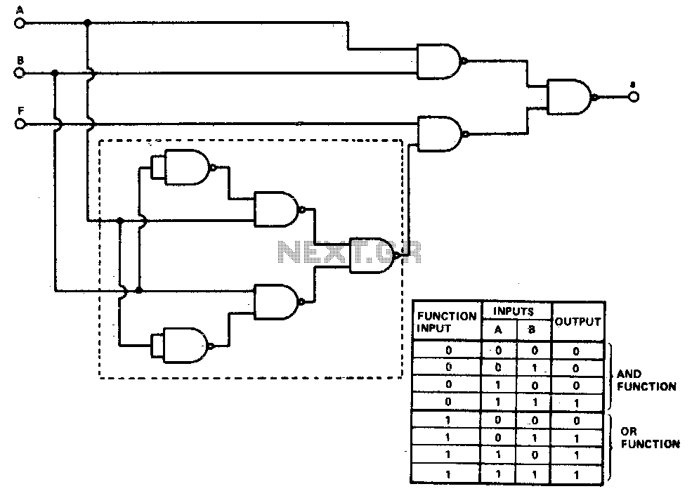
This gate converts an AND gate or an OR gate by applying a logic 1 on the function input. The logic design utilizes eight two-input NAND gates. The number of gates may be reduced by replacing the five NAND...
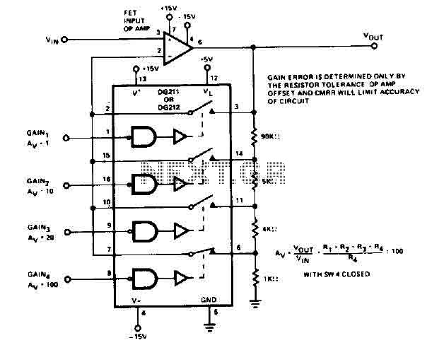
The circuit utilizes the DG212 to control gain through the use of resistors. To calculate the various gain levels, switch SW4 must be closed. Gain error is influenced solely by the tolerance of the resistors, the offset of the...
Often, there is a need for an additional telephone ringer in an adjacent room to indicate an incoming call. For instance, if the telephone is located in the drawing room, an extra ringer may be required in the bedroom....