
Programming PIC 16F84A

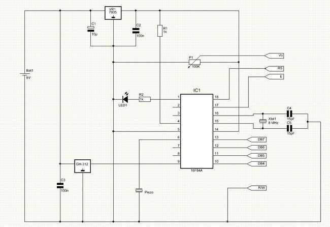
The analysis of the PIC microcontroller's configuration begins with a thorough examination of its datasheet, which serves as a critical resource for understanding the operational parameters and pin assignments. For instance, bit 3 of Port B (RB3) is essential for specific applications and is located at pin 9 in the DIP and SOIC packages. The significance of accurately interpreting the pin diagram, as illustrated in Table 1-1 of the datasheet, cannot be overstated. It provides a visual representation of the microcontroller's layout, which is vital for correct circuit design.
When reviewing the provided schematic, it is important to approach it with a critical mindset. The presence of errors may indicate either a misunderstanding of the schematic's intent or a pedagogical strategy employed by the instructor to promote independent learning. Identifying these errors is a valuable exercise, as it reinforces the importance of the datasheet as a primary reference document.
In debugging the associated code, the MPLAB Simulator serves as an invaluable tool. By stepping through the code, one can monitor the values assigned to each register, ensuring they align with the expected outcomes. This process not only facilitates the identification of logical errors but also enhances the understanding of the microcontroller's operation. Engaging with the datasheet and simulator in this manner fosters a deeper comprehension of electronic design and programming, ultimately leading to more robust and functional circuit implementations.After answering all those questions, to yourself, and geting the answers and/or decisions on that, some serious studying of the PIC datasheet is the next step ion order to know what the steps for each configuration and other details. Not quite. It is bit 3 of Port B, not pin 3 which is RA4. RB3 is on pin 9 of the PIC (for the DIP & SOIC packages). Look at the pin diagram (Table 1-1) in the data sheet. Still, the schematic you posted has many thing wrong. Are you sure this is exactly as your lecturer gave it to you Or maybe the errors are on purpose to see if you read the data sheet to get this circuit to work. Therefore we`ll point out the errors but not the solutions, that`s up to you to learn. As to whether the code might work, use the MPLAB Simulator to Step through your code. When you step through the code check that every register gets the value it should. This should always be to first step in debugging and will catch many `dumb` errors. 🔗 External reference
Related Circuits
The PIC16C57-RCT is a communication single-chip microcomputer integrated circuit that is commonly utilized in the Qiao Xing series of IC card management telephones. The PIC16C57-RC integrated circuit features a pulse and dual-tone dialing circuit, memory data and clock circuit,...
This clock timer utilizes a PIC16F628 microcontroller to display a 3.5-digit time format and control an external load. It is programmable to time intervals from 1 to 59 minutes. The clock features a calendar that accounts for leap years...
The idea behind this project is to provide some means of loading a program into a PIC that will then be able to program other PICs in a more conventional way. How do you program a PIC to be...
The following circuit illustrates a Water Level Detector Circuit Diagram. This circuit is based on the PIC12F683 microcontroller. Features include the ability of the PIC microcontroller to enter a sleep mode. The Water Level Detector Circuit utilizing the PIC12F683 microcontroller...
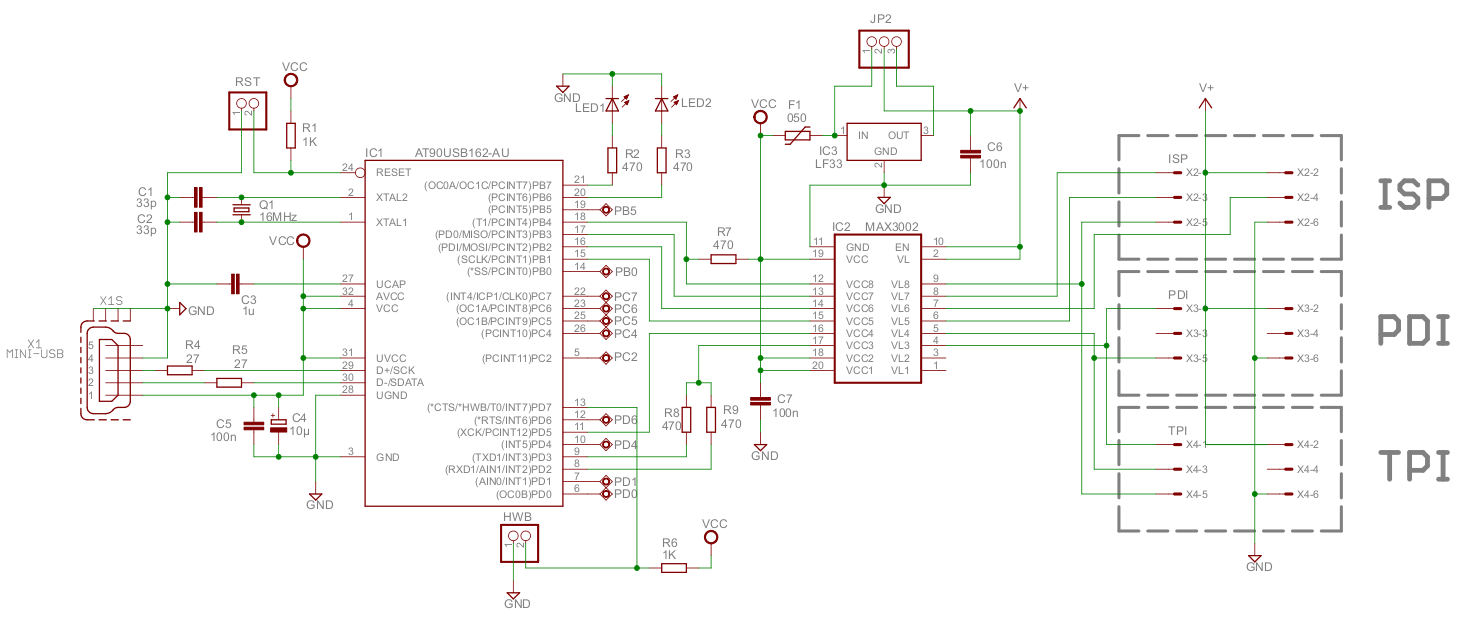
Atmel's XMEGA series of microcontrollers are compact devices featuring a high-speed clock, extensive I/O options, USB connectivity, and up to 8 UART ports. They serve as an effective intermediary between AVR and PIC microcontrollers and the more powerful ARM...
This is a gas detecting circuit capable of sensing many different types of gases. The sensor used is the GH-312 and from the datasheet it is capable of sensing gases like smoke, liquefied gas, butane and propane, methane, alcohol,...