
Water Level DetectorCircuit Based On The PIC12F683

The Water Level Detector Circuit utilizing the PIC12F683 microcontroller is designed to monitor water levels in a tank or reservoir. The circuit operates by employing sensors that detect the presence or absence of water at predefined levels. The PIC12F683 serves as the central processing unit, managing the input from the sensors and controlling the output signals accordingly.
The circuit typically consists of several components, including the PIC12F683 microcontroller, water level sensors, resistors, capacitors, and a power supply. The water level sensors can be implemented using conductive probes or float switches, which send signals to the microcontroller when water reaches specific thresholds. The microcontroller processes these inputs and can activate visual indicators, such as LEDs, or audible alarms to inform users of the water level status.
In addition to its primary function, the circuit can be designed to enter a low-power sleep mode to conserve energy when the water level is stable. This feature is particularly beneficial in applications where power efficiency is crucial, such as in remote installations or battery-operated devices.
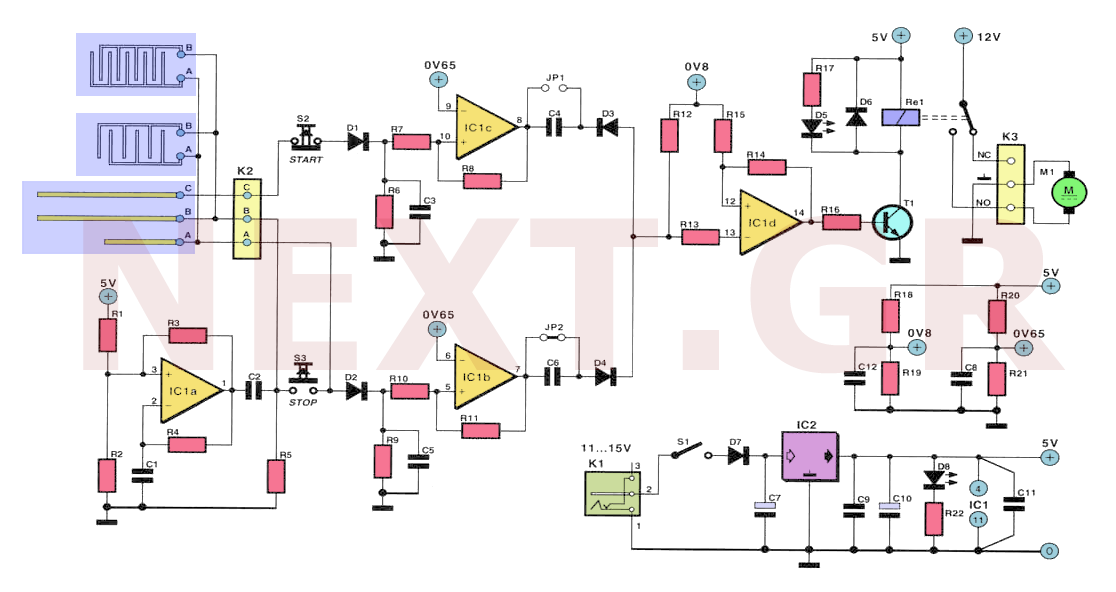
The schematic should clearly illustrate the connections between the microcontroller and the sensors, as well as the power supply configuration. Proper attention should be given to component specifications to ensure reliable operation. Overall, the Water Level Detector Circuit based on the PIC12F683 microcontroller provides a robust solution for monitoring water levels effectively.The following circuit shows about Water Level Detector Circuit Diagram. This circuit based on the PIC12F683. Features:PIC Micro has the sleep .. 🔗 External reference
Related Circuits
Collecting rainwater for garden use and grey water domestic applications is both ecologically and economically beneficial. Enthusiasts often utilize large underground tanks for storage. A challenge arises in determining the water level without manually opening the tank hatch. One...
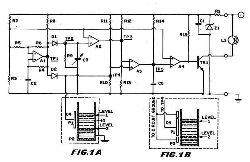
Figure 1 (A) depicts the circuit diagram of one embodiment of the fluid level detector designed. The circuit is typically powered by a 12-volt automobile battery, which is reduced to a 5-volt DC source using a voltage regulator consisting...
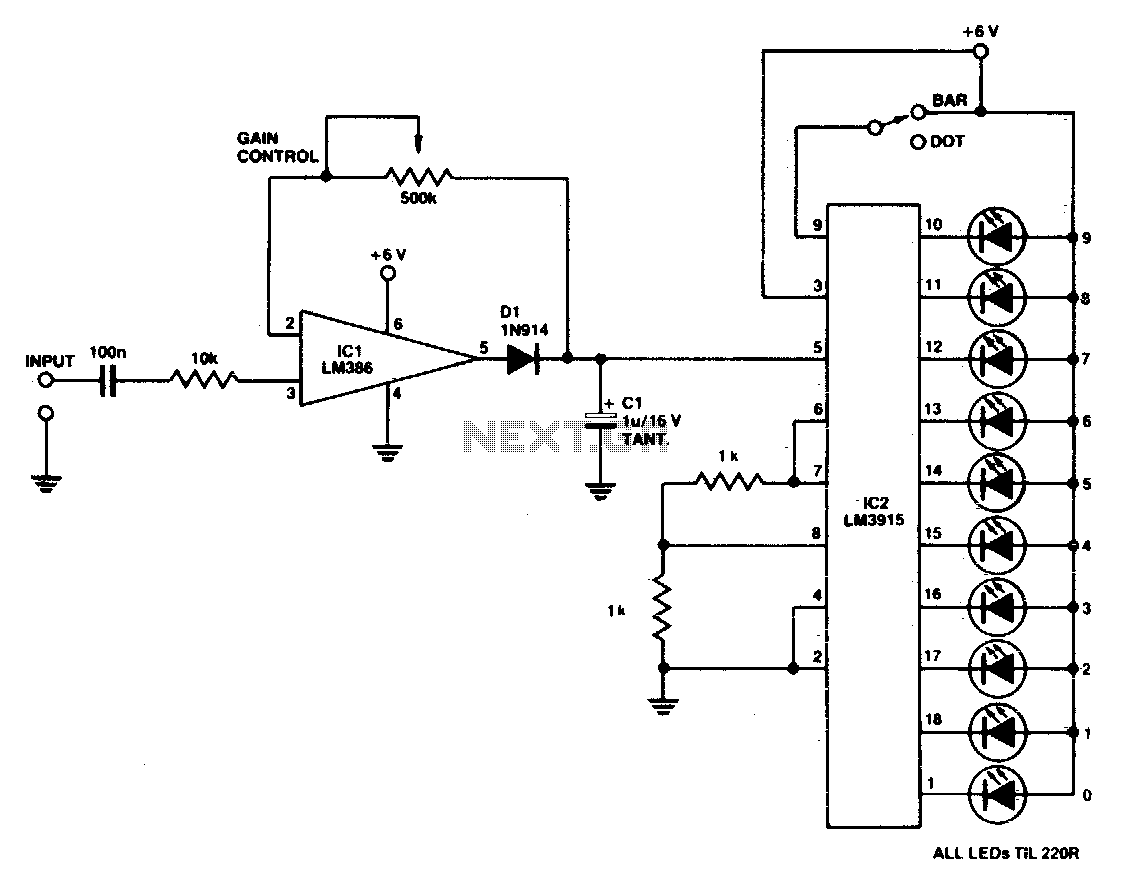
A simple power meter can be configured to provide a bar or dot display for a hi-fi system. Green LEDs are used for levels 0 to 7, yellow for level 8, and red for levels 9 to indicate peak...
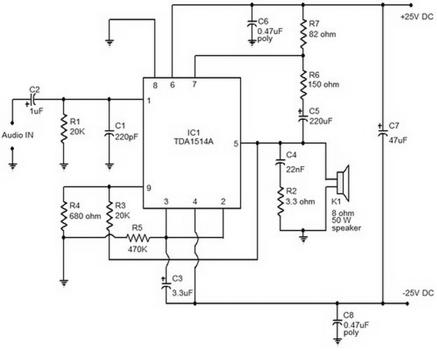
This document provides a circuit diagram of a car stereo. It includes a circuit diagram of a Class B 15 Watts audio amplifier designed using a dual op-amp and a transistor. The 15 W Class B audio amplifier circuit...
Often, for various reasons, individuals forget or are unable to water the plants in their homes. Many humidity sensor units merely alert users with a beeping sound or a flashing light when the pot requires watering. However, what if...
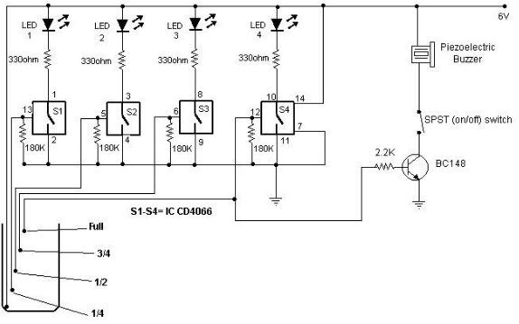
A low-cost water level indicator circuit can be designed using this schematic. This water level indicator utilizes a CMOS IC, the CD4066, to indicate the amount of water present in an overhead tank and provides an alarm when the...