
Project

The LM56 Thermostat circuit utilizes the LM56 integrated circuit, which is designed for low-power applications requiring temperature control. The primary function of this circuit is to monitor temperature and provide corresponding digital outputs based on predefined threshold levels. The circuit operates by utilizing a voltage divider configuration formed by the resistors R1, R2, and R3, which sets the reference voltage levels for the temperature thresholds VT1 and VT2.
In the circuit, the internal voltage reference of the LM56 (1.250 volts) is divided down to create the reference voltages that correspond to the desired temperature set points. The values of R1, R2, and R3 can be calculated using the following equations:
1. VT1 = Vref * (R2 / (R1 + R2))
2. VT2 = Vref * (R3 / (R2 + R3))
Where Vref is the internal reference voltage of the LM56. The output behavior of the LM56 is defined such that when the measured temperature exceeds the upper threshold (T1), output 1 transitions to a low state, indicating that the temperature is above the setpoint. Conversely, when the temperature drops below T1, output 1 returns to a high state, allowing for control actions or notifications to be triggered.
The hysteresis feature is essential for preventing rapid toggling of the output state around the threshold temperature, providing stability in the control system. The internal temperature sensor and voltage comparators enhance the functionality of the LM56, allowing for precise temperature monitoring and control.
This circuit can be utilized in various applications, such as HVAC systems, refrigeration units, and other temperature-sensitive equipment, where reliable temperature regulation is crucial. The design simplicity and effectiveness of the LM56 thermostat make it an excellent choice for engineers and hobbyists seeking to implement temperature control solutions in their projects.The values of LM56 Thermostat project Circuit diagram of R1, R2 and R3 for the points of travel, VT1 and VT2 can be determined using the subsequent equations. This thermostat of electronic circuit with IC LM56 diagram what simple project, you can use as reference.
As you know, IC LM56 is correct double output thermostat low power characterized by National Semiconductors. trip temperature stable 2 points called VT1 and VT2 are made with dividing the LM56 IC 1, 250 reference internal voltage volts by three outside resistors (R1, R2 and R3) component. There are 2 digital outputs for LM56 IC which is that output1 becomes weak when the temperature increases over T1 and goes high when the temperature decreases below (temperature T1 ±Hysteresis).
Component IC LM56 has a variety of useful features as internal voltage reference internal temperature sensor, 2 internal voltage comparators, etc. 🔗 External reference
Related Circuits

Autopilot for model helicopters, with 3-axis IMU/INS and GPS. The autopilot system designed for model helicopters integrates a three-axis Inertial Measurement Unit (IMU) and Inertial Navigation System (INS) along with Global Positioning System (GPS) functionalities. The IMU comprises accelerometers and...

The LTC3113 fixed frequency buck-boost DC-DC converter can be utilized to design various power supply circuits that operate with input voltages that are above, below, or equal to the output voltage. The topology integrated into the IC ensures low...

A simple 5-volt switching power supply electronic circuit project can be designed using the FAN302HL, a highly integrated PWM controller integrated circuit. This IC provides several features that enhance the performance of general flyback converters. The constant-current control of...

To create a full-scale Tesla Coil that produces at least 6 inches of sparks, also referred to as "artificial lightning." Current Status: The project was successful, with a complete full-scale, full power test conducted on Friday, July 15, 2011....
This sound-activated switch allows for control through sound, which can be beneficial not only in robotics but also in home automation applications. The sound-activated switch operates by detecting specific sound frequencies or patterns, typically using a microphone or a sound...
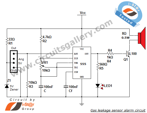
This article discusses a home security alarm circuit designed to detect LPG gas leakage. The circuit utilizes a gas sensor module, SEN 1327, which incorporates a QM 6 gas sensor. The output signal from this gas sensor module is...