
Proximity Alarm I Circuit

IC1 functions as a critical component in a security system or alarm device, leveraging the interaction between its oscillators and amplifier to create a responsive alert mechanism. The low-frequency audio signal oscillator serves as the primary sound generator, producing a tone that is amplified for audible output through a speaker. This audio output is essential for alerting users to a potential security breach or other significant events.
The high-frequency oscillator's design is deliberately unstable, which allows it to remain inactive until it detects changes in the RC network. The combination of R2 and PL forms a variable resistor, where decreasing the resistance of PL enhances the oscillator's sensitivity. This sensitivity is crucial for detecting even minor changes in capacitance, which can occur when a person approaches the antenna loop. The capacitance introduced by the loop, along with the inherent capacitance of the human body, effectively activates the high-frequency oscillator.
Once activated, the high-frequency oscillator triggers the low-frequency oscillator, resulting in the generation of an audio tone. The latching feature of the IC ensures that once the alarm is triggered, it remains active until the power supply is interrupted. This design prevents accidental deactivation and ensures that alerts are reliably communicated. Overall, the integration of oscillators and amplifiers in IC1 creates a robust mechanism for detecting and signaling events, making it an effective element in various electronic applications. IC1 contains several oscillators and an amplifier. The low-frequency audio-signal oscillator is used to supply an input to the amplifier. That signal is the audio tone that is amplified, then supplied to the speaker by the amplifier. The high-frequency oscillator is purposely set to be very unstable. It is dormant or off` until the resistor-capacitor (RC) network is changed. The resistance (R) in this case is made up of R2 and PL As the resistance of PI is decreased, the unit becomes more sensitive (more unstable), and less capacitance (C) is needed to cause the oscillator to oscillate. The capacitance required is provided by C2 and by any capacitance introduced via the antenna loop. When you come near that loop, your inherent body capacitance causes the high-frequency oscillator to begin to oscillate, which then causes the low-frequency oscillator to be switched on internally. Once the alarm is sounding, the IC is designed so that it latches, that is, it stays on until the power to it is switched off.
Related Circuits

The power controller operates from the vehicle's accessory switch, allowing the load to receive power only when the ignition key is in the "on" position. A momentary pushbutton controls a load of up to 10 A using half of...
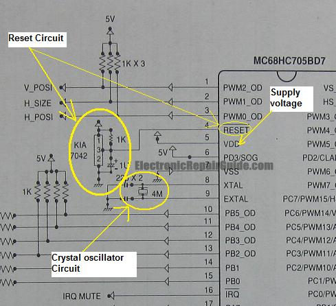
The difference between these two ICs. A microcontroller is a specialized type of microprocessor designed to be self-sufficient and cost-effective, while a microprocessor is typically intended for general-purpose use, such as in personal computers (PCs). The microcontroller integrates several...
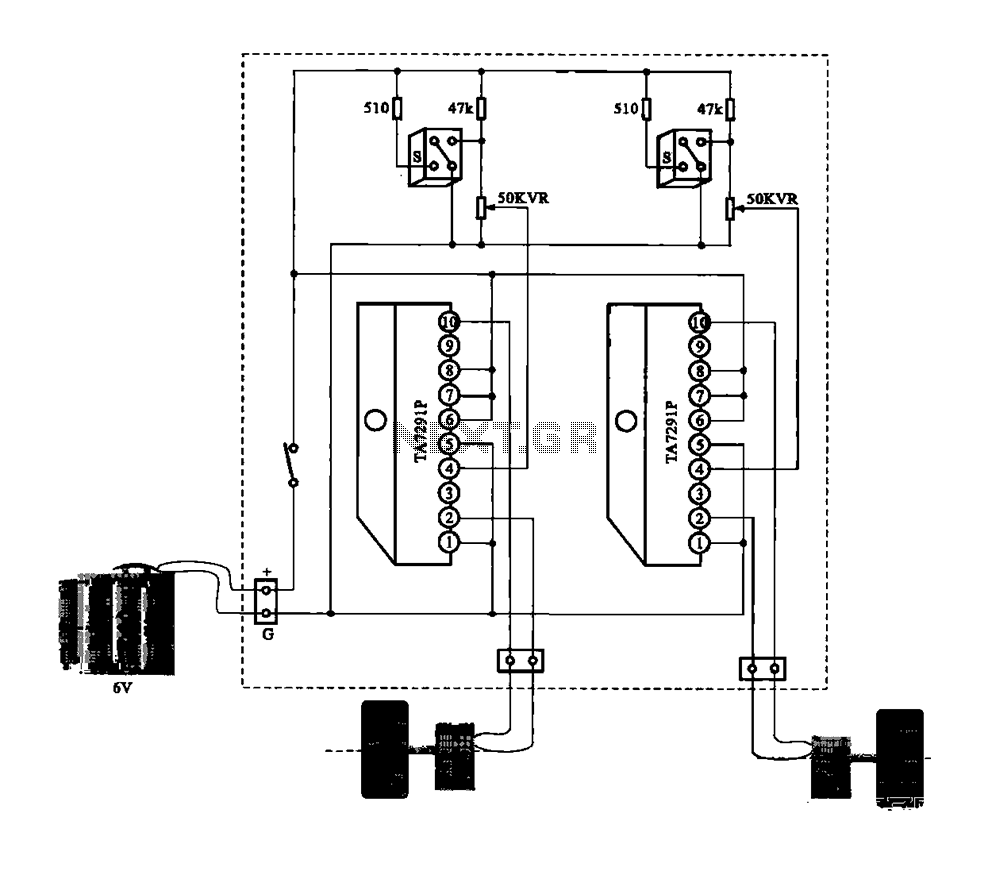
A dual motor drive circuit for automatic tracking consists of two motors that are part of a car structure, which operates based on the principles of a double motor drive system. The dual motor drive circuit is designed to facilitate...
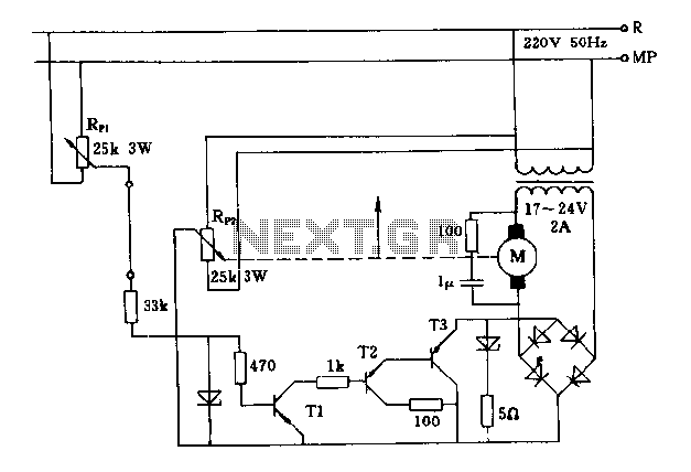
The FIG potentiometer RP2 has a sliding contact that is directly connected to the antenna. The system operates such that only when potentiometers RP1 and RP2 are positioned identically, do the non-conductive transistors and rectifier bridge remain off, resulting...

When the system is placed in a shop or mall, logos and product advertisements serve as an ideal complement to temperature information. For home use, photographs of children at the beach or, should the temperature drop, images of making...
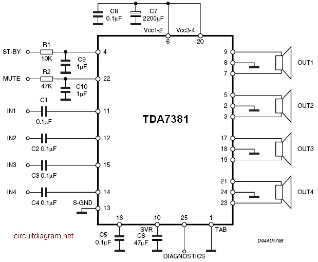
The amplifier is a quad amplifier circuit (amplifier with four inputs and four outputs) based on the TDA7381. This amplifier is designed for car audio systems, but it can also be utilized for other applications. The circuit has a...