
Satellite receiver antenna servo control circuit diagram

The described circuit involves a dual potentiometer setup, specifically RP1 and RP2, which are critical for controlling the position of an antenna through a motor. The sliding contact of potentiometer RP2 is mechanically linked to the antenna, allowing for direct positional feedback.
In this configuration, both potentiometers must be aligned to ensure that the system remains inactive, meaning that no power is supplied to the motor. This is achieved through the use of non-conductive transistors that are controlled by the voltage output from the potentiometers. The rectifier bridge plays a vital role in converting AC to DC voltage, but in this scenario, it remains off when the potentiometers are not in the same position.
When the potentiometers are not aligned, the system activates the motor, allowing the antenna to adjust its position in accordance with the reference set by the potentiometers. This synchronous rotation mechanism ensures that the antenna can follow the desired positional reference accurately. The design emphasizes the importance of maintaining alignment between the two potentiometers to prevent unintended movement of the antenna, which could lead to misalignment in applications such as radio frequency transmission or reception.
This circuit exemplifies a feedback control system where precise adjustments can be made based on the relative positions of the potentiometers, ensuring that the antenna remains in the optimal position for its intended function. The careful arrangement of components, including the potentiometers, transistors, and rectifier bridge, is crucial for the reliable operation of the system.FIG potentiometer RP2 sliding contact with the axle shaft is directly connected to the antenna. Only when given potentiometer RP1 and RP2 refers in the same position, only non- conductive transistors, rectifier bridge off, no voltage on the motor, the antenna stationary, otherwise the motor or antenna will follow the reference potentiometer synchronous rotation.
Related Circuits
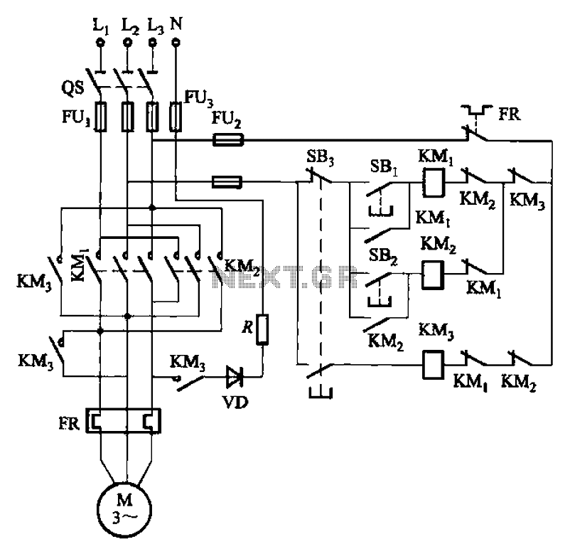
The circuit illustrated in Figure 3-145 employs a rectifier diode brake for neutral grounding in a three-phase, four-wire power supply system. This circuit design incorporates a rectifier diode brake, which plays a crucial role in ensuring the safety and reliability of...
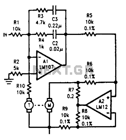
The tachometer, mounted on the same shaft as the DC motor, functions as a generator, producing a DC output voltage that is proportional to the motor's speed. A summing amplifier, labeled as Al, manages its output to ensure that...
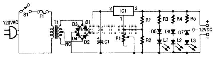
This 0- to 12-Vdc variable power supply utilizes an integrated circuit (IC) voltage regulator along with a robust transformer to deliver a dependable DC power output. The schematic illustrates that transformer T1 has a primary voltage of 120 V...
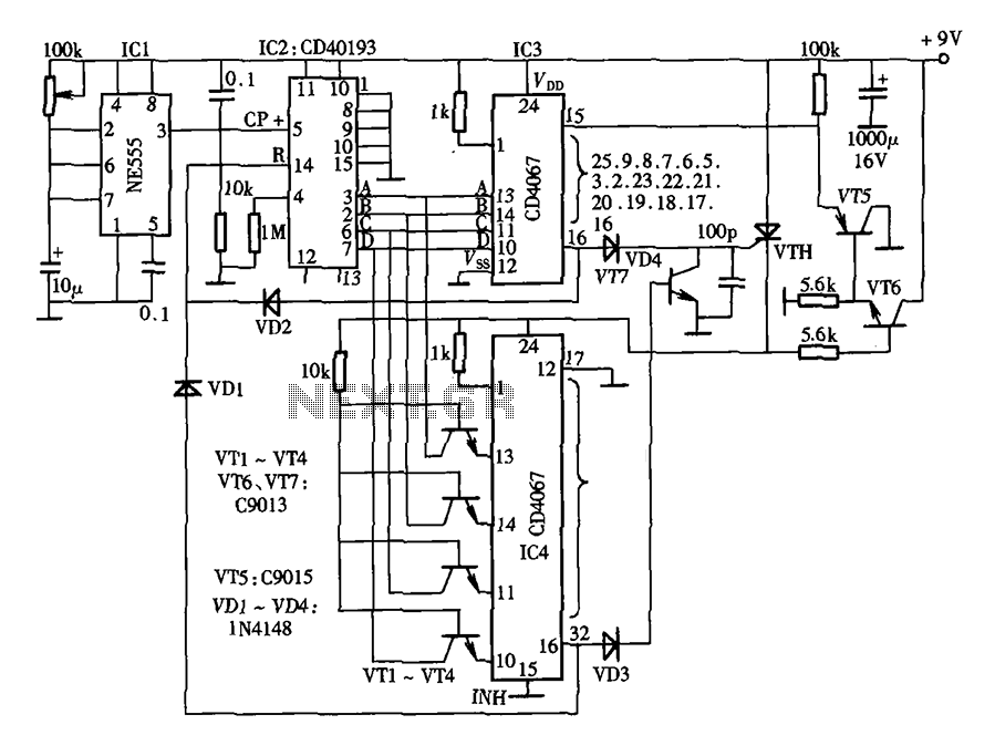
The lantern control circuit allows for the management of 30 outputs through an external driver circuit, specifically designed for water sports or large decorative lantern applications. The circuit features a control pulse generator, which regulates the lights, and an...
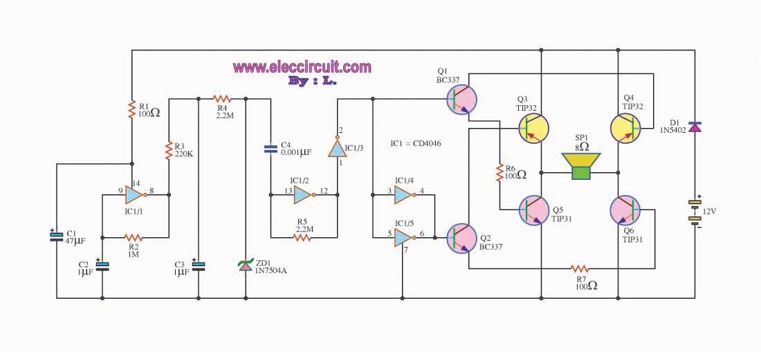
This is a simple siren sound generator with high power output and significant noise levels. The circuit utilizes digital integrated circuits (ICs), specifically the CD4046, in an inverter configuration along with four transistors to increase the current output to...
Incremental rotation or linear encoders are widely used, but they typically do not provide a direction signal. This design presents a straightforward method to detect forward or reverse direction. Incremental encoders usually generate two output signals, referred to as...