
pull up and pull down resistor

In digital electronics, understanding the behavior of floating inputs is crucial for reliable circuit operation. A floating input is one that is not connected to a definite voltage level, and it can pick up noise, leading to unpredictable states in digital logic devices. To avoid this, pull-up and pull-down resistors are employed.
In a pull-up resistor configuration, the resistor is connected between the input pin of the logic IC and the positive supply voltage (Vcc). This ensures that when the input is not actively driven low, it defaults to a high state (logic 1). Conversely, in a pull-down configuration, the resistor connects the input pin to ground, ensuring that the input defaults to a low state (logic 0) when not driven high.
The choice of resistor value is important for balancing power consumption and response speed. A 10 kΩ resistor is commonly used as it provides a good compromise between current draw and response time. Lower resistor values will result in higher current consumption, while higher values may lead to slower response times due to increased resistance to rapid voltage changes.
In summary, proper handling of floating inputs through the use of pull-up or pull-down resistors is essential in digital circuit design to ensure predictable behavior and efficient power management.Most of the beginners in digital electronics assume that the hanging input is a logic 0. Then, that`s a misconception. They are neutral state which can be a logic 0 or a logic 1. This will bring chaos on your circuit operation. As you can see, in each case there is a default input. For a pull-up, the default input to the logic IC is 1. And for the pull-down, the logic is 0. The resistor also provide a current limiting function thus affecting power consumption of the input section. 10kohms is the commonly value but any value can be use depending on your application. 🔗 External reference
Related Circuits
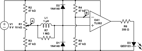
The circuit above is a canonical AC coupled common emitter amplifier, which is typically used as a linear amplifier rather than a switch that activates when the input exceeds a certain level. The AC coupled common emitter amplifier is...
A simple count-down LED timer that counts in minutes and seconds. Three buttons below the LED provide control of the unit, allowing you set the desired countdown time in minutes and seconds and a start/stop button. Completion of the...
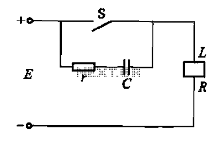
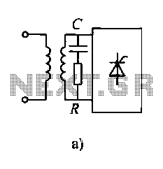
A resistor-capacitor circuit designed to prevent spark blowout. The coil's magnetic energy is converted into electrical energy stored in the capacitance C, effectively suppressing sparks and enhancing safety. The circuit is capable of functioning normally even with reverse polarity....
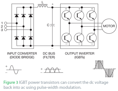
An AC drive controls AC induction motors and, similar to its DC counterparts, regulates speed, torque, and horsepower. A DC drive typically manages a shunt-wound DC motor, which features separate armature and field circuits. This teardown of the Schneider...
Diodes and thyristors have limited tolerance to over-current and over-voltage conditions. Short-term exposure to excessive voltage or current can damage these components and prevent them from achieving their full potential. The parameters of these devices should be determined based...
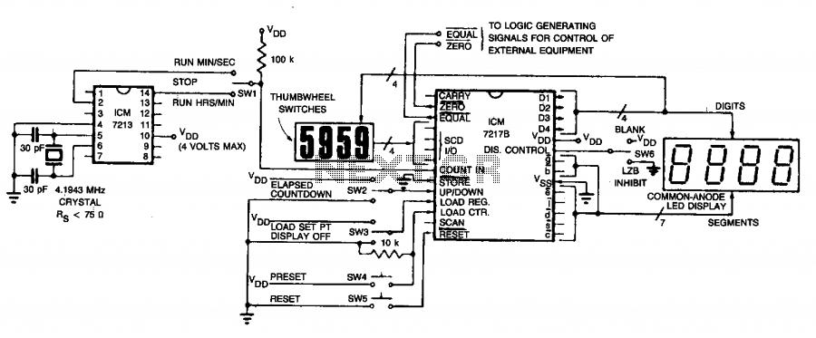
The circuit employs an ICM7213 precision timebase generator with a frequency of 4.1943 MHz, which is utilized for generating pulses that are counted by an ICM7217B counter. Thumbwheel switches are incorporated to allow the user to input a starting...