
How to calculate the resistors and capacitors for an amplifier circuit

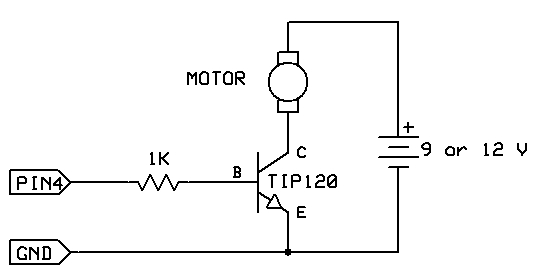
The AC coupled common emitter amplifier is a fundamental configuration utilized in analog electronics for amplifying weak signals. This circuit typically consists of a bipolar junction transistor (BJT) configured in a common emitter arrangement, where the input signal is applied to the base terminal of the transistor through a coupling capacitor. This capacitor serves to block any DC component of the input signal while allowing AC signals to pass through, ensuring that the transistor operates in its linear region.
In this configuration, the transistor's collector is connected to a power supply through a load resistor, while the emitter is often grounded or connected through an emitter resistor, which can improve stability and linearity by providing negative feedback. The output is taken from the collector, where the amplified signal is available for further processing.
The design of this amplifier requires careful selection of component values, including the biasing resistors that set the operating point of the transistor, ensuring it remains in the active region for the entire input signal swing. The coupling capacitors at both the input and output stages are chosen based on the desired frequency response, allowing for effective amplification of signals within a specified bandwidth while attenuating unwanted frequencies.
Additionally, the circuit can be enhanced with bypass capacitors to improve high-frequency performance and stability. The overall gain of the amplifier can be adjusted by modifying the load resistor and the emitter resistor, allowing the designer to tailor the circuit to specific applications.
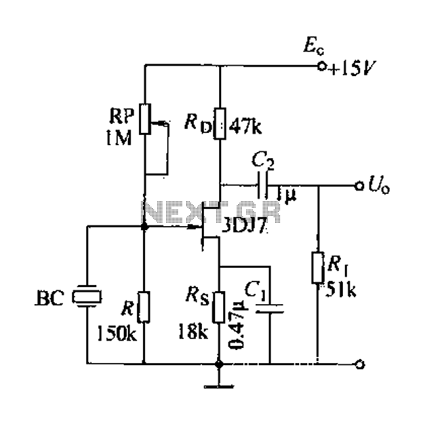
This configuration is widely used in various applications, including audio amplification, signal processing, and as a building block for more complex analog circuits.The circuit above is the canonical AC coupled common emitter amplifier which is typically used as a linear amplifier, not a switch that "turns on" when the input is above some level. Alfred Centauri Apr 9 `13 at 19:26 Edit you question to reflect what you`re trying to do, I have an answer but I need to make sure I understand what you`re asking
first. Matt Young Apr 9 `13 at 19:37 🔗 External reference
Related Circuits
This delay can be used in power amplifiers to prevent the fuses from failing when the amplifier is turned on. The circuit is very simple with a relay that is turned on when C2 and C3 are charged. If...
A field effect transistor (FET) voice amplifier has a low input impedance, approximately 1 kΩ, requiring the signal source to provide a constant current signal for operation. Unlike bipolar transistors, FETs are voltage-controlled devices that draw minimal current at...
The car parking sensor circuit utilizes a photodiode as the distance sensor. It measures the distance between adjacent sensors. The car parking sensor circuit employs photodiodes to detect the proximity of obstacles, enhancing parking safety and convenience. Photodiodes are semiconductor...
The circuit requires a double pole, double throw relay in conjunction with a single transistor to allow toggling the relay with a momentary push button. One set of relay contacts is used to control the load, while the other...
The strategy involves assembling the circuit in stages, testing each component as it is integrated. Once all connections are established and can be controlled or read correctly by the computer, the main program can be developed with assurance that...
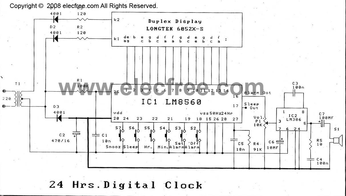
The digital time clock circuit is of great interest to electronic amateurs. The most popular clock ICs include the LM8361 and MM5387. Unfortunately, these ICs... The digital time clock circuit serves as an essential component for various electronic applications, providing...