
Pulse Charger for reviving tired Lead Acid batteriess

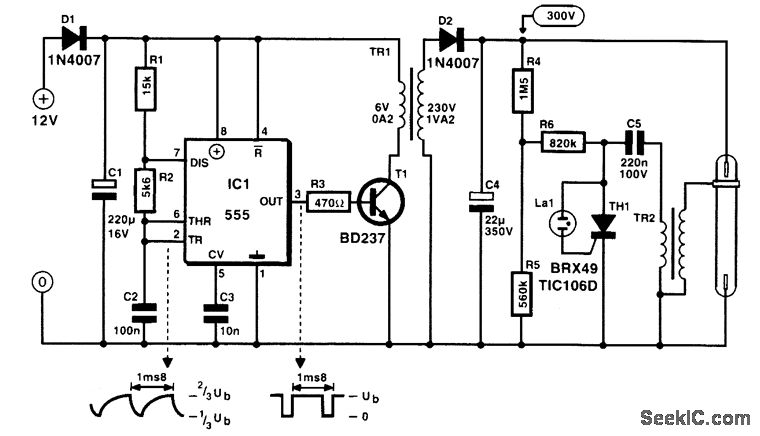
This project involves the design and implementation of a desulfation circuit for lead-acid batteries, focusing on enhancing the performance and longevity of the batteries used in various vehicles and equipment. The circuit is built around a modified charger, which includes essential components such as a transformer, rectifier, and control circuitry. The use of a 555 timer and a triac driver allows for precise control over the charging pulses, enabling the application of higher voltages in short bursts. This method promotes the dissolution of sulfate crystals without causing excessive heating or damage to the battery.
The circuit's design emphasizes safety and efficiency, with recommendations for component specifications to ensure reliable operation. The integration of a snubber circuit protects the triac from voltage spikes, while the choice of a robust bridge rectifier enhances the overall performance of the charger. The project also highlights the importance of monitoring the charging process, as variations in battery condition may affect the results. By carefully adjusting pulse durations and observing the battery's response, users can optimize the desulfation process for their specific needs.
Overall, this desulfation circuit provides a valuable solution for maintaining lead-acid batteries, extending their life, and improving their performance in various applications.Before you begin a project like this remember: mains voltage is dangerous so if you are not 100% sure of what you ’re doing consult a friend who has the skills or, don ’t do it at all ! If you own a motorcycle, a motor home, a caravan, a lawn mover, a day cruiser or maybe a vintage car you must at some point had to write off a lead acid b
attery. When a battery is improperly charged or allowed to self-discharge as occurs during non-use, sulphate crystals build up on the battery`s plates. The sulphate preventing the battery from being fully charged and therefore it is unable to deliver its full capacity.
When trying to charge a battery in this state it only gets hot and looses water, the gravity of the electrolyte is not increasing to its normal full charge ” state. The only thing you do is killing the battery completely. If a battery has a resting voltage of at least 1. 8 Volts/cell and no cells are shorted, desulphation of its plates can be done. This circuit is an add-on and part for a modification of a normal charger and it takes care of the sulphate problem.
The project: get hold of an old charger, big or small it ’s your choice depending on the size of batteries you normally handle (bigger is better). There are some tricks to boost the performance if you need it. Start by ripping out everything except the transformer and the rectifier. Some older chargers are equipped with fin rectifiers, which have high voltage drop and must be replaced.
Replace with a rugged bridge rectifier that can cope with the amperes. All wiring on secondary should be short and heavy wire. The rectifier should be bolted to the chassis to keep cool. If the charger have a high/low switch it ’s a bonus, if not you can in some cases add a few turns of wire on the secondary winding. The circuit; a 14-stage ripple counter and oscillator IC 4060 produce a pulse, which is the heartbeat of the circuit.
The pulse is feed to the 555 timer that deicide the length of the active output. With the switch you can select long or short pulse output. The output of the 555 timer triggers the zero-cross optoisolator triac driver MOC 3041 via a transistor. This gives the charger transformer a soft start via the triac and the snubber circuit. A small power supply is necessary for the circuit and consists of T1 a transformer 15V 0. 1A secondary, a bridge rectifier, a regulator and two caps. Because this project include a charger that is (X) the outcome can differ in performance from one case to another.
However this do not mean that your project doesn ’t work, but the efficiency can vary. Some notes the snubbercap is a high voltage AC type (X) and the resistors on the mains side is at least 0. 5W type. Use a triac that can take 400V+ and 10A+, I use BTA 25. 600 but this is overkill in most cases. No PCB sorry! Well the short version. The object is to get the cell voltage high enough for the sulphate to dissolve without boiling or melting the battery.
This is achieved by applying higher voltage for shorter periods and let the battery rest for a while. The pulses on short range is about 0. 5s on / 3s off and the long pulse range is 1. 4s on / 2s off. These times can vary depending on component tolerances. Start on long pulse and if you discover boiling ” (more than with normal charging) in the electrolyte switch to short puls.
Don ’t leave the process unattended, at least until you know how your specific version of this project turns out. I built ver. 1 of this circuit some 10 years ago and have experimented with it but I ’m sure someone can improve it further.
🔗 External reference
Related Circuits
The phone is a Siemens S65. The official charger that came with the phone specifies an output of 5V at 420mA. However, actual performance may vary from the printed specifications. Voltage measurements indicated that without the phone connected, the...

A constant voltage battery charger is required, with an output of 44V and a maximum current of 1A. This charger will be integrated into the battery compartment of an e-bike and will maintain a permanent connection to the three...
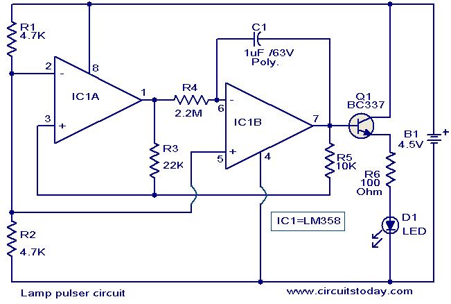
This circuit is designed to gradually pulse an LED or a low-power filament lamp, creating a visual effect where the light transitions from an OFF state to full brightness and then back down to OFF. Such a circuit is...
The NCP5810D is a dual-output DC/DC converter capable of generating both positive and negative voltages. This device is optimized for powering modules such as AMOLED display drivers, where high output voltage accuracy, regulation, signal integrity, and compact design are...
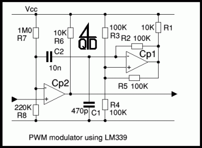
The first example utilizes a standard op-amp oscillator circuit to produce a triangular waveform, which is then level-shifted and supplied to a comparator (e.g., LM339) to generate a PWM waveform. It is common for users to prefer using two...
BD237 datasheet. Selling leads from all over the world, ChinaICMart is the world's largest IC trading marketplace on the internet. It offers the best suppliers for BD237, and users can also download the datasheet for BD237. The BD237 is a...