
Pulse Width Modulators using LM339

The described circuit employs an operational amplifier (op-amp) configured as an oscillator to generate a triangular waveform. This waveform serves as the basis for pulse-width modulation (PWM) signal generation. The triangular waveform is level-shifted to ensure it operates within the appropriate voltage range for the subsequent comparator stage. The comparator, such as the LM339, is utilized to compare the triangular waveform against a reference voltage.
In this configuration, two comparators are employed to enhance performance and flexibility. The first comparator is responsible for determining the rising edge of the PWM signal, while the second comparator manages the falling edge. This dual-comparator setup allows for more precise control over the duty cycle of the PWM signal.
The triangular waveform is generated by the op-amp in an astable multivibrator configuration, where the feedback network sets the frequency of oscillation. The output of the op-amp is then level-shifted using a simple resistor network or a dedicated level-shifting circuit, ensuring that the voltage levels are compatible with the input requirements of the comparators.
The output from the comparators produces a PWM waveform, which can be utilized in various applications such as motor control, dimming of LED lights, and other power modulation tasks. The duty cycle of the PWM signal can be adjusted by varying the reference voltage applied to the comparators, thus providing a method to control the average power delivered to the load.
This circuit exemplifies a robust approach to generating PWM signals, leveraging the characteristics of op-amps and comparators to achieve effective signal modulation.The first example uses the standard op-amp oscillator circuit to generate a triangular waveform which is level-shifted and fed to a comparator (e. g. LM339) to give the PWM waveform. Most people will want to use two comparators rather than one op-amp and one comparator so that is what we show here.
Disclaimer All files are found using legitimate se arch engine techniques. This site does not and will not condone hacking into sites to create the links it list. We will and do assume that all links found on the search engines we use are obtained in a legal manner and the webmasters are aware of the links listed on the search engines. If you find a URL that belongs to you, and you did not realize that it was "open to the public", please use the report button to notify the blogmaster of your request to remove it or it will remove within 24 hours.
This is not an invitation for webblog haters to spam with requests to remove content they feel that is objectionable and or unacceptable. Proof of URL ownership is required. NOTICE: This Blog Has Already Been Reviewed And Accepted By Blogger. com 🔗 External reference
Related Circuits
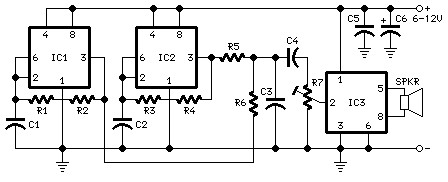
The following diagram is the schematic diagram for a car horn circuit, which can be utilized for car modifications. Components List: R1 = 68K, R2 = 2K2, R3 = 56K, R4 = 3K3, R5, R6 = 4K7, R7 =...
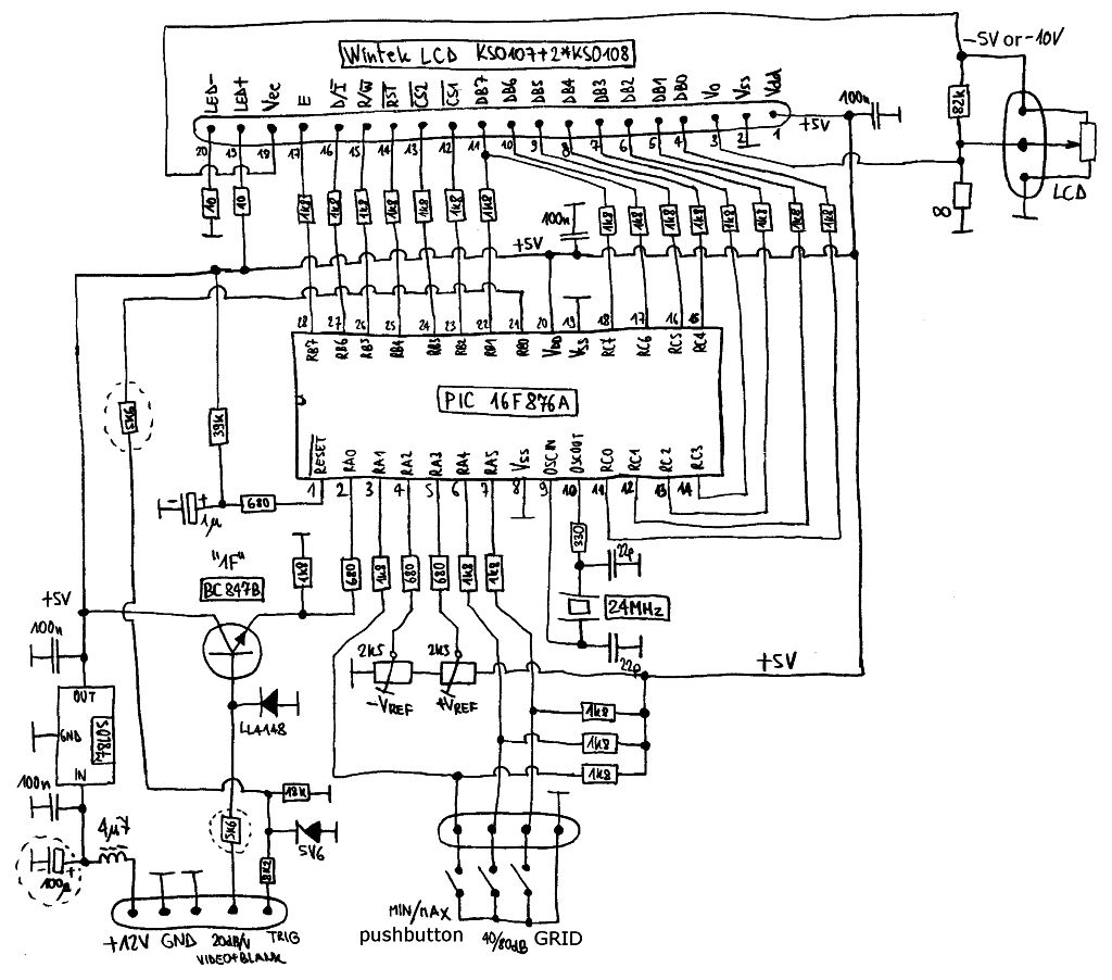
Spectrum-analyzer project 2007 update. Since the development of the wide-band VCO almost 10 years ago, the entire spectrum-analyzer project has progressed significantly. The spectrum analyzer project initiated in 2007 focuses on the development and enhancement of a wide-band Voltage Controlled...
Before starting a project of this nature, it is crucial to remember that mains voltage is hazardous. If there is any uncertainty regarding the procedure, it is advisable to consult someone with the appropriate skills or refrain from proceeding...
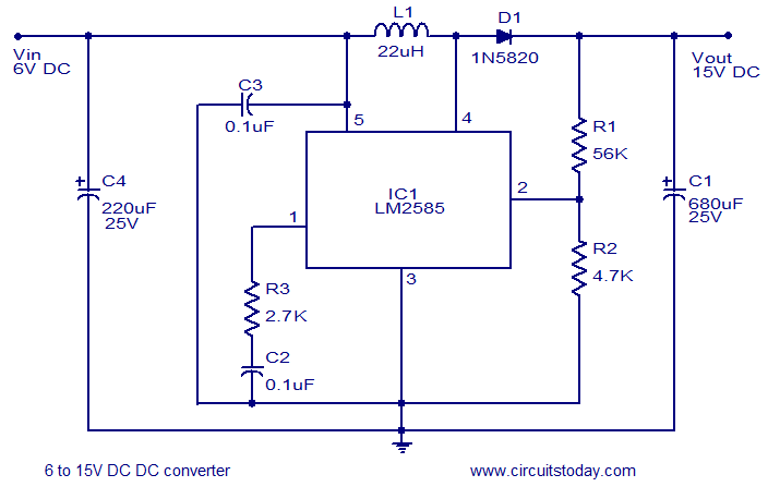
A simple and efficient 6 to 15V boost/step-up DC to DC converter based on IC L2585. This voltage converter circuit requires few external components. The circuit utilizes the L2585 integrated circuit, which is designed for high-efficiency voltage boosting applications. The...
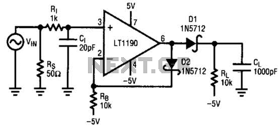
A fast pulse detector can be constructed using this circuit. A very fast input pulse will surpass the amplifier's slew rate, resulting in a prolonged overload recovery time. Implementing some degree of dv/dt limiting on the input can alleviate...
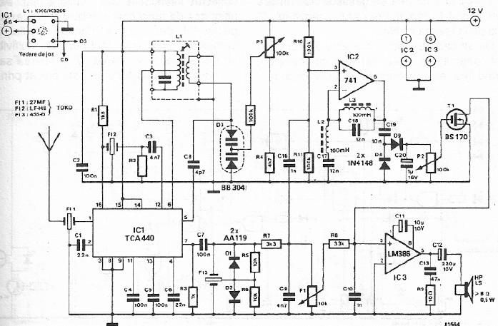
A simple FM CB radio receiver can be constructed using the electronic diagram provided. This FM CB radio receiver circuit utilizes a TCA440 integrated circuit and operates at an intermediate frequency of 455 kHz. The input filter is a...