
Pulse Frequency Modulator

The compact pulse cum frequency modulator utilizes a comparator IC, designated as IC1, to modulate the pulse width effectively. The modulation process involves adjusting the change-over point of the comparator, which is influenced by an external control voltage. This control voltage determines the threshold at which the comparator switches states, thereby altering the duration of the output pulse.
In practical applications, the control voltage can be generated using a potentiometer or a digital-to-analog converter (DAC), allowing for precise adjustments to the pulse width. The output of the comparator can be connected to various components, such as transistors or operational amplifiers, to drive loads or further process the signal.
The design may also include filtering stages to smooth out the output waveform or to limit the frequency response, ensuring that the modulated signal meets the required specifications for its intended application. The compact nature of the modulator allows it to be integrated into various electronic systems, providing flexibility in signal processing tasks.
Overall, this circuit can be utilized in applications such as pulse-width modulation (PWM) for motor control, signal generation for communication systems, or as part of a more complex modulation scheme in RF applications.The pulse width of the compact pulse cum frequency modulator can be varied by altering the change-over point of comparator IC1 with a control voltage via.. 🔗 External reference
Related Circuits
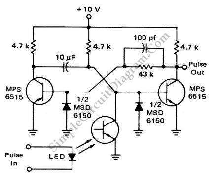
This is a flash-triggered (photo-driven) circuit that produces a pulse with a constant predetermined width. This circuit can be used to control any device. The flash-triggered circuit operates by utilizing a photodetector, which is typically a photodiode or phototransistor, to...
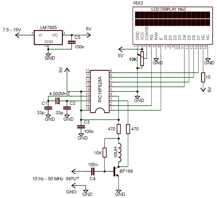
The frequency meter is capable of measuring frequencies ranging from 10 Hz to 60 MHz, with a precision or resolution of 10 Hz. It can be utilized to assess the frequency of various devices such as oscillators, transmitters, frequency...
This is a high-frequency switch circuit. This circuit utilizes the 2N4391 transistor. When in the off state, it provides a high off-impedance of less than 0.2 pF and exhibits a low on-resistance. The high-frequency switch circuit designed with the 2N4391...
This LOGIC PULSER capable of delivering pulses of various compositions, to any type of circuit you wish to test. Basically it is designed to complement the LOGIC PROBE and can be used in situations where the LOGIC PROBE is...
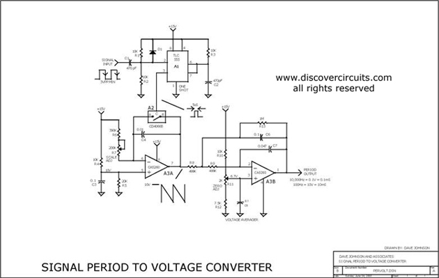
This circuit is designed to convert a square wave input signal into a voltage output. The voltage produced is proportional to the time interval between the edges (period) of the signal, rather than its frequency. The operational range of...
This result places the oscillator within the UK FM Band, which ranges from 87.5 to 108 MHz. If L1 is equipped with an adjustable ferrite core, its inductance can be modified, allowing for fine tuning. If L1 consists of...