
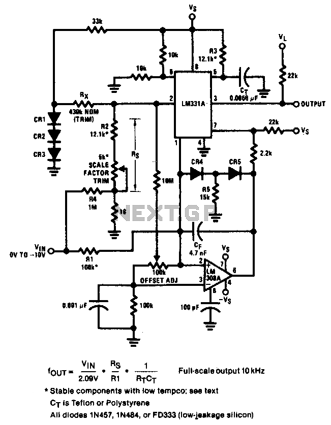
PULSE PERIOD TO VOLTAGE CONVERTER

The circuit operates by using a timing mechanism that captures the duration of the square wave's high and low states. A monostable multivibrator can be employed to generate a pulse width that corresponds to the input signal's period. This pulse width is then fed into a voltage scaling circuit, which could be a resistor divider or an operational amplifier configured to amplify the voltage to the desired range.
The input square wave signal is connected to the trigger of the monostable multivibrator. When the signal transitions from low to high, the multivibrator generates a pulse whose width is determined by the time the input signal remains high. This pulse width is then converted into a proportional voltage using a resistive network or an op-amp circuit, which can be calibrated to output between 100mV and 10V based on the specified period range.
To ensure stability and accuracy, the circuit may include filtering components, such as capacitors, to smooth out any noise from the input signal. Proper selection of the multivibrator and voltage scaling components is crucial to achieve the desired performance characteristics. The use of a single 15V power supply simplifies the design and reduces the overall cost, making this circuit an efficient solution for applications requiring period measurement in various electronic systems.This is a test circuit converts a square wave input signal into a voltage. But, the voltage produced is proportional to the time between edges (period) of the signal, not the frequency. The range is from 100uS to to 10mS, which produces a voltage from 100mV to 10 volts. Other scale factors are also possible. The circuit is powered from single 15v supply and uses inexpensive parts. It is great when a signal`s period instead of its frequency needs to be monitored. Source: discovercircuits 🔗 External reference
Related Circuits
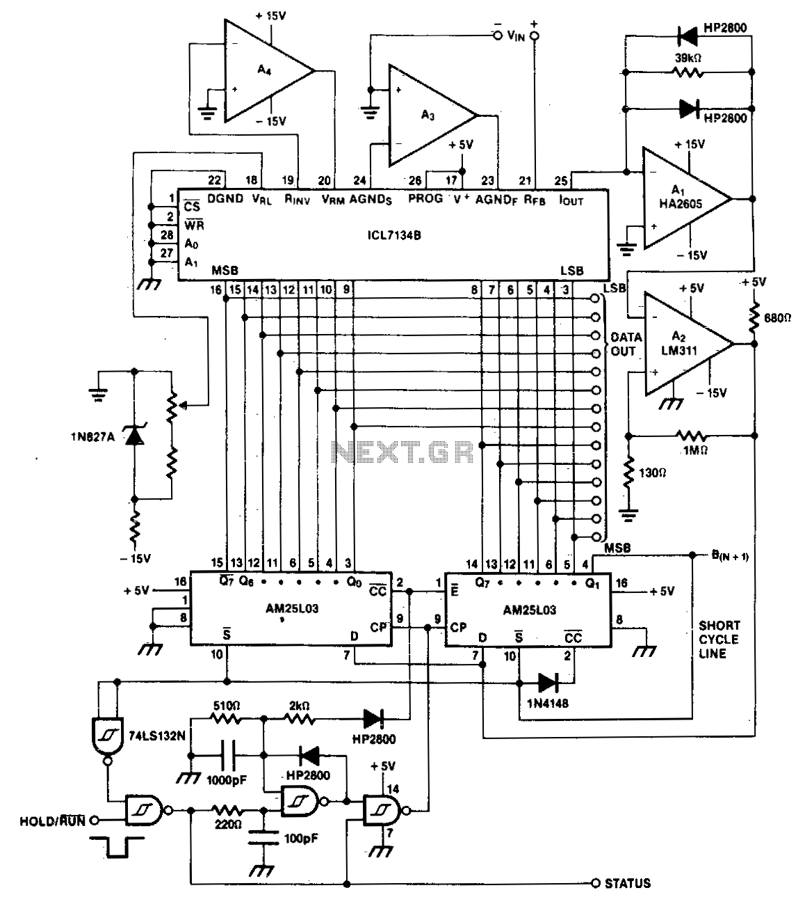
A bipolar input, high-speed A/D converter utilizes two AM25L03 devices to create a 14-bit successive approximation register. The comparator consists of a two-stage circuit featuring an HA2605 front-end amplifier, which is employed to minimize settling time issues at the...
The circuit achieves an error of better than 0.02% and a nonlinearity of 0.003% within a ±20°C range around room temperature. The circuit's design focuses on precision and linearity, making it suitable for applications that require high accuracy in temperature...
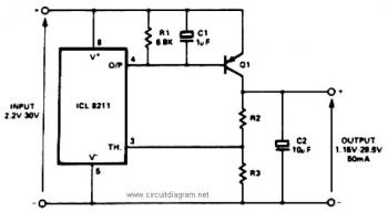
The IC8211 serves as a voltage reference and regulator amplifier, with Q1 likely functioning as the series pass transistor. R1 determines the output current of the IC8211, while C1 and C2 contribute to loop stability and help suppress the...
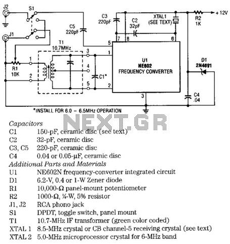
The NE602 chip, U1, contains oscillator and mixer stages. The mixer combines the oscillator signal with the input RF signal to produce signals whose frequencies are the sum and difference of the input frequencies. For example, an 8.5-MHz oscillator...
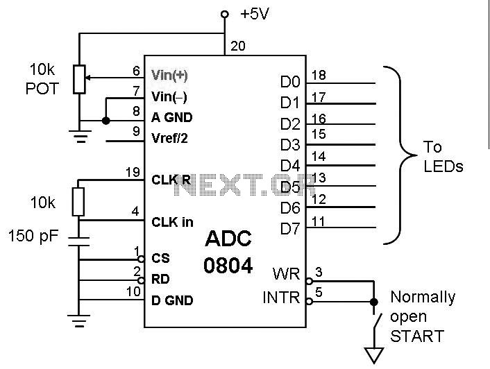
This post discusses the interfacing and operation of Analog-to-Digital Converters (ADCs). An ADC is a device that converts the analog signals from transducers into digital signals, enabling computers to process the data. ADCs are essential for obtaining meaningful results...
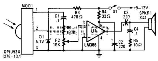
This circuit utilizes an infrared pulse-to-audio converter to assist in troubleshooting infrared remote controls, making it an effective tool for detecting infrared light sources. It employs a photo cell module (Radio Shack P/N 276-137) to detect IR radiation and...