
Pulse Generator And Signal TracerCircuit

The circuit operates as a versatile testing tool for audio and RF applications, leveraging a complementary astable multivibrator configuration that allows for adjustable frequency output. The choice of components, particularly resistors R3 and capacitors C2 and C3, plays a critical role in establishing the desired pulse frequency, while the output waveform is refined by diode D1 for symmetry. The dual functionality of the circuit, transitioning from pulse generation to audio amplification, is facilitated by the incorporation of J1, which not only serves as a connection point for headphones but also integrates a switching mechanism that alters the circuit's operation based on the presence of a load.
For optimal performance, careful consideration of component ratings is essential, particularly when interfacing with high-voltage devices. The current consumption characteristics indicate efficient operation in both modes, allowing users to maintain prolonged testing sessions without significant power drain. The inclusion of a small ceramic capacitor when using longer leads mitigates potential RF interference, ensuring signal integrity during testing. The design's adaptability to various load impedances enhances its usability across different applications, making it suitable for a wide range of audio and RF testing scenarios. Overall, this circuit serves as a valuable asset for engineers and technicians engaged in the testing and troubleshooting of electronic devices.This simple circuit generates narrow pulses at about 700-800Hz frequency. The pulses, containing harmonics up to the MHz region, can be injected into audio or radio-frequency stages of amplifiers, receivers and the like for testing purposes. A high-pitched tone can be heard from the speaker of the device under test when all is working properly.
Th e clip must be connected to the ground of the device under test, touching with the probe the different stages of the circuit, starting from the last stage and going up towards the first. When the tone is no longer heard, the defective stage has been found. Connecting an earclip or headphone to J1, the circuit will automatically change into a two-stage amplifier and any audio signal coming from the device under test and picked-up by the probe will be heard through the headphones.
The testing of a circuit should be made in the reverse manner, i. e. starting from the first stage and going down until the last stage. When nothing is heard, the defective stage has been found. Q1 & Q2 form a complementary astable multivibrator, whose operating frequency is set mainly by R3, C2 & C3 values. Output pulses are taken at Q2 Collector and applied to the probe by means of decoupling capacitor C1.
D1 provides a symmetrical shape for the output waveform. If an earclip or headphone jack is plugged into J1, the connection from Q2 Collector and C1 - C2 is broken by the switch incorporated into J1: in this case the circuit becomes a two-stage amplifier. If you intend to use the circuit to test valve operated devices C1 must be a 630V type. Working with low voltage supply transistor devices the voltage of C1 can be lowered to 63 or 100V. If instead of a short probe, you intend to connect the circuit to the device under test by means of a piece of wire longer than a few centimeters, a small ceramic capacitor (470 to 1000pF) should be added in parallel to D1 to prevent unwanted RF oscillation.
Current drawing when in Pulse-Generator mode is about 60 µA and 1. 2mA when in Signal-Tracer mode operation. Therefore SW1 can be omitted, provided that the earclip or headphones are unplugged when the circuit is unused. J1 is a stereo switched jack socket wired to obtain a series connection of the two earpieces forming a stereo headphone.
In this manner the circuit is loaded with a higher impedance and sensitivity will be improved. Therefore, the higher the load impedance the more sensitive the Signal-Tracer. In any case, common 32 Ohm impedance mini-headphones suitable for walkman sets will work fine. 🔗 External reference
Related Circuits
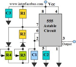
The astable multivibrator circuit lacks a stable state. In the absence of an external signal, the internal transistors alternately switch between cutoff and saturation at a frequency determined by the RC time constants of the coupling circuits. Therefore, an...
This circuit generates sine waves ranging from 1 kHz to 25 kHz with a total harmonic distortion (THD) of better than -80 dB. It comprises a 4th-order low-pass filter and a TTL counter. The circuit utilizes a sine wave oscillator...
This tiny circuit comprising of a single 3 terminal IC UM66 can be built small enough to be placed inside a greeting card and operated off a single 3V flat button cell. There is not much to the circuit....

Generators that do not use fuel to operate provide 24 hours of electricity for continuous use. In the early days of this invention, a significant issue arose: the battery powering the generators would deplete within 20 to 30 minutes...
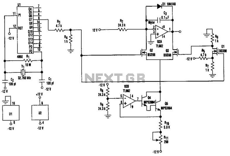
U2-a, U3, and R2 function as an integrator. Q2 and Q3 are alternately switched at 256 cycles. U2-b, Q4, Q5, and R8 through R11 form a constant current generator, with R11 configured to produce a symmetrical triangular waveform. The circuit...
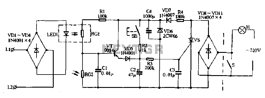
Diodes VD8 to VDI1 function as part of the main circuit isolation, with SCR serving as a composition control switch. The buck regulator circuit is composed of a stable orbital tube VD6 and a simple resistor-capacitor combination (C4). The...