
Clock-Driven Triangle-Wave Generator Circuit

The circuit described involves a combination of operational amplifiers and transistors to achieve specific signal processing functions. The integrator circuit comprising U2-a, U3, and R2 is designed to integrate the input signal over time, producing a voltage output that is proportional to the area under the input waveform. This is particularly useful in applications where the accumulated value of a signal is required, such as in analog computing or signal conditioning.
Transistors Q2 and Q3 are utilized as switches that alternate at a frequency of 256 cycles. This switching action is critical for controlling the operation of the integrator, allowing it to reset periodically or change its operational state, thereby influencing the output waveform characteristics.
The second part of the circuit involves U2-b, Q4, Q5, and resistors R8 through R11, which collectively act as a constant current generator. This configuration is essential for maintaining a steady current flow regardless of load variations, ensuring that the subsequent stages of the circuit operate reliably. Resistor R11 is specifically calibrated to produce a symmetrical triangular waveform, which is a common requirement in waveform generation applications. The triangular waveform is characterized by its linear rise and fall times, making it suitable for various applications, including modulation and signal processing.
Overall, this circuit exemplifies an integrated approach to signal processing, combining integration and waveform generation in a cohesive design. The careful selection of components and their configuration enables precise control over the output characteristics, making it applicable in a wide range of electronic applications. U2-a, 03 and R2 operate as an integrator. Q2 and Q3 are alternately switched at 256 cycles. U2-b, Q4, Q5, and R8 through Rll arc a constant current generator, and Rll is set for a symmetrical triangular waveform.
Related Circuits
This circuit detects AC line currents of approximately 250mA or greater without establishing any electrical connections to the line. The current detection occurs through an inductive pickup (L1) constructed from a 1-inch diameter U-bolt wound with 800 turns of...
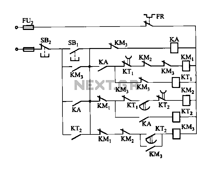
Figure 3-118 illustrates an automatic acceleration control circuit. This circuit employs a male contactor time relay, enabling the motor to start automatically at a low speed before transitioning to high-speed operation. The automatic acceleration control circuit depicted in Figure 3-118...
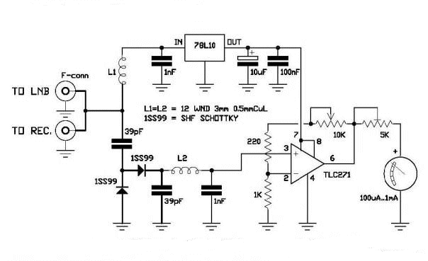
A circuit has been identified that integrates a voltage regulator and filter to isolate the voltage supplied by the receiver for powering an operational amplifier (op-amp) that drives a meter. Additionally, the circuit isolates the carrier frequency from the...
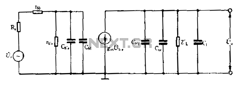
Common emitter amplifier circuit with resistance and capacitance coupling. The common emitter amplifier circuit is a fundamental configuration in analog electronics, widely utilized for its ability to amplify voltage signals. This circuit employs a bipolar junction transistor (BJT) as the...
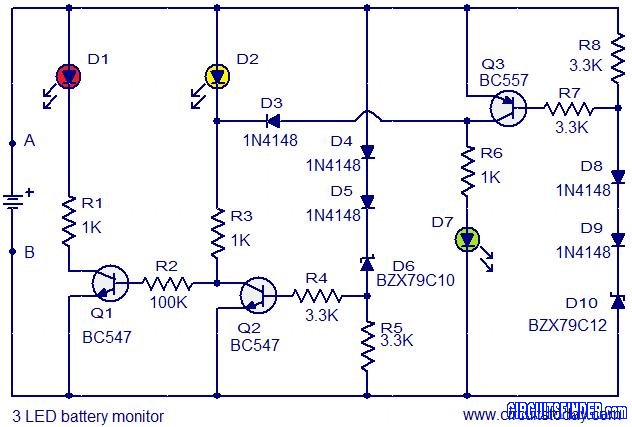
This is the circuit diagram of a 3 LED bar graph type battery monitor circuit that is ideal for monitoring the voltage level of an automobile battery. When battery voltage is 11.5V or less, transistor Q1 will be on...
Descriptions of the various modules in a home-built music synthesizer - Sub-oscillator project. The sub-oscillator module in a home-built music synthesizer serves a crucial role in enriching the sound by generating lower frequency signals that complement the primary oscillators. This...