
Pulse signal generating circuit

The circuit described involves the implementation of pulse signal generators using operational amplifiers (op-amps), which are versatile components frequently employed in analog electronics. These circuits can generate a variety of pulse waveforms, including square waves, triangular waves, and sawtooth waves, depending on the configuration of the op-amps and associated passive components.
A common configuration for generating a square wave involves the use of a comparator circuit. In this setup, an op-amp is configured with a feedback resistor and a capacitor. The capacitor charges and discharges through the resistor, creating a voltage that oscillates between two thresholds. The output of the op-amp switches states when the input voltage crosses these thresholds, resulting in a square wave output.
For triangular wave generation, an integrator circuit can be constructed using an op-amp. This configuration takes the square wave output from the comparator and integrates it over time, producing a linear ramp up and down, which results in a triangular waveform at the output.
In a sawtooth wave generator configuration, a combination of an integrator and a comparator can be used. The output from the integrator, which ramps up linearly, is fed into a comparator that resets the integrator when it reaches a certain threshold. This creates a sawtooth waveform, characterized by a linear rise followed by a sudden drop.
These pulse signal generating circuits can be adjusted for frequency and amplitude by varying the values of the resistors and capacitors in the circuit. The ability to produce different types of pulse signals makes these circuits valuable in various applications, including signal processing, timing applications, and waveform generation for testing electronic devices. Proper design considerations, including power supply decoupling and component selection, are essential for ensuring stable and reliable operation of these pulse generating circuits.It shows the use of various forms of pulse signal generating circuit operational amplifier.
Related Circuits
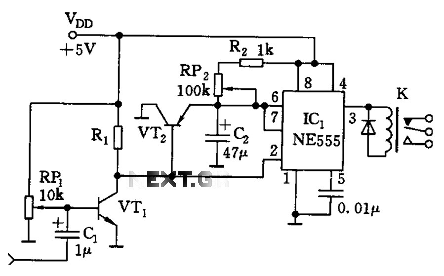
The circuit consists of a sound detection circuit and a monostable trigger circuit that activates a relay. VT1 amplifies the input audio signal. When a signal is detected, the 555 timer is triggered, pulling K. Simultaneously, VT2 conducts, allowing...
This circuit is a motion detection sensor that utilizes a light source and a detector in the form of an infrared motion detector. The motion sensor employs an infrared LED and a phototransistor. The sensitivity of the sensor can...
The purpose of this circuit is to animate shop windows using a capacitive sensor placed behind a postcard-like banner. The card is positioned against the glass inside the shop window, allowing visitors to activate the relay by placing their...
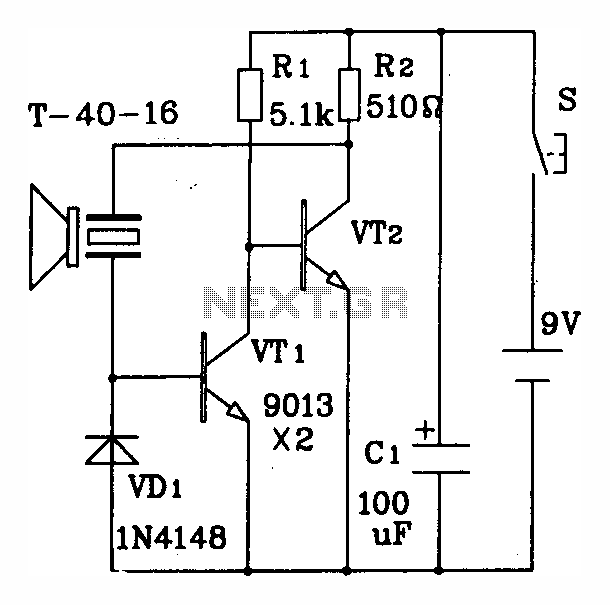
The discrete components ultrasonic transmitting circuit T/R-40-16 is capable of emitting a series of ultrasonic signals at a frequency of 40 kHz. This circuit operates at a voltage of 9V, with an operating current of 25 mA, and can...
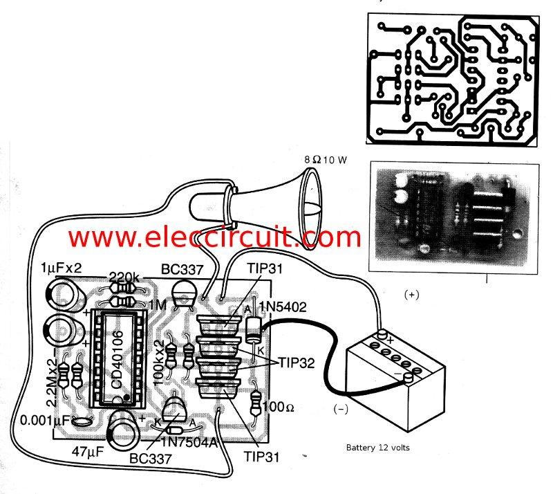
This is a simple siren sound generator with high power output and significant noise. The circuit utilizes digital ICs, specifically the CD4046, in an inverter configuration, along with four transistors to amplify the current output to a horn speaker...
The individual has been engaged in garden railroading for just over a year, utilizing skills from various hobbies. They have designed and built two scratch-built bridges and nearly 100 trestle bents to support a 200-foot main line. Their interests...