
Voice relay circuit

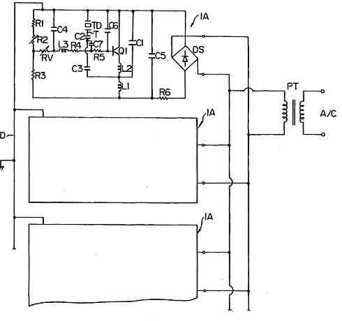
The circuit described integrates a sound detection mechanism with a monostable trigger for controlling a relay. The sound detection circuit employs a transistor (VT1) to amplify incoming audio signals, ensuring that even low-level sounds can be processed effectively. Upon detection of a sound signal, the 555 timer is activated, which subsequently triggers the relay.
The configuration of the 555 timer in monostable mode allows it to output a single pulse when triggered. The relay (K) serves as an actuator, enabling control of higher power devices in response to sound detection. VT2 plays a crucial role by conducting current during the pulse, which facilitates the rapid discharge of capacitor C2 through both the internal discharge path of the 555 timer and through VT2. This ensures that the output pulse is clean and devoid of noise that could arise from slow discharges.
After the sound signal is no longer present, both transistors (VT1 and VT2) cease conduction, leading to a charging phase for capacitor C2. The rate at which C2 charges is influenced by the resistors R2 and RP2, where R2 provides a fixed resistance and RP2 is a variable resistor allowing for fine-tuning of the delay time. The time constant of the monostable circuit, represented by td, is determined by the equation 1.1 (R2 + RP2) C2, which indicates that the delay can be adjusted between 0.05 to 0.5 seconds depending on the resistance values set by RP2.
This configuration is particularly useful in applications where a temporary activation is required in response to sound, such as in alarm systems, automatic lighting, or other control systems that require a delay before deactivation. The ability to adjust the delay time provides flexibility in various applications, making this circuit a versatile solution for sound-activated control systems. As shown, the circuit by the sound detection circuit and the monostable trigger circuit, the actuator for the relay. VT1 complete input audio signal amplification, when the sig nal comes, 555 set, K pull. Meanwhile, VT2 conduction, the charge on C2 through the interior of the discharge tube 555 and VT2 immediately discharged. After the sound, VT1, VT2 off, C2 through R2, RP2 charging it monostable circuit transient stability time td l.1 (R2 RP2) C2, delay range from 0.05 to 0.5 seconds, and can be adjusted by RP2 .
Related Circuits

This is a simple 555 timer circuit suitable for oscillating applications. To slow down the strobe effect, replace the 220 µF capacitors with 1000 µF capacitors. For a faster strobe effect, use a 150 µF capacitor. Additionally, R1 can...
A remote-operated spy robot circuit can be controlled using a wireless remote controller. It captures audio and video information from the surroundings and transmits this data to a remote station via RF signals, with a maximum range of 125...
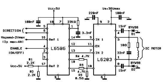
The L620x is a monolithic full bridge switching motor driver implemented using the new Multipower-BCD technology. This technology enables the integration of multiple isolated DMOS power transistors along with mixed CMOS/bipolar control circuits. The L620x series includes various versions:...
This decibel meter circuit responds to sound pressure levels ranging from approximately 60 to 70 dB (decibels). The sound is captured by an 8-ohm speaker and amplified using a transistor stage along with an LM324 operational amplifier section. A...
The Johnson 275 watt and Kilowatt Matchboxes are often seen as exaggerated and unfairly criticized. They are neither exceptional tuners nor poorly designed. The main drawbacks include the fixed coupling link and the fact that they are balanced voltage...
Ultrasonic atomizer circuit: How to generate an atomized water mist using ultrasonic sound waves. The ultrasonic atomizer circuit is designed to produce a fine mist of water by utilizing ultrasonic sound waves. This process involves the conversion of electrical energy...