
Pulse Width Modulation

The control of electric motors in model building applications necessitates a comprehensive understanding of both the electrical characteristics of the motors and the control methods employed. The use of PWM offers a sophisticated approach to managing motor speed and performance, mitigating issues associated with traditional control methods. The integration of 555 timer ICs into the circuit design enables precise frequency generation and duty cycle manipulation, which are crucial for achieving smooth motor operation.
In practical applications, the design of the PWM circuit begins with configuring the 555 timer in astable mode, where the timing components—resistors and capacitors—determine the frequency of the output signal. The duty cycle can be adjusted using potentiometers, allowing for fine-tuning of the motor speed. The output from the 555 timer is then fed into a transistor circuit, which acts as a switch to control the power delivered to the motor. By varying the duty cycle of the PWM signal, the average voltage supplied to the motor can be modulated, resulting in variable speed control.
Additional considerations in the design include ensuring that the components can handle the current and voltage levels required by the motor. Heat dissipation and protection circuitry, such as diodes for back EMF protection, are also critical to maintaining circuit integrity and prolonging component life. The choice of components, including the type of motor used, will influence the performance characteristics of the entire system, necessitating careful selection based on the specific application requirements.
Overall, the application of PWM in motor control within Meccano model building not only enhances performance but also allows for greater flexibility in design, enabling builders to create more complex and dynamic models.The control of electric motors is something which interests nearly everyone involved with Meccano model building. Every model has its own motor requirements with regard to the space available, the power of the motor, its speed, whether it must stop and start frequently, and the need for reduction gearing.
On the face of it, simple methods of contr ol are perfectly adequate, with a regulated voltage supply, a simple on/off switch, and the means to reverse the motor. Speed can be controlled with a wire-wound potentiometer (variable resistor) or a circuit such as the Darlington Pair Speed Control.
In reality, these methods can provide very unrealistic results. The main problem is poor starting performance, the motor tending to jump almost instantly from a stationary position to what is often more than half speed. The main cause of this seems to be the starting characteristic of the motor itself which when under load seems reluctant to start.
A motor has a relatively low resistance when it is stationary. As the speed control is advanced, the current through the motor increases, but the voltage across the motor remains quite low. The speed control therefore has to be well advanced before the voltage and power fed to the motor are high enough to overcome its reluctance to start.
As the motor speed and the load on it changes, there are changes in its internal resistance. Speed regulation is not very good under these circumstances, particularly at low speed. A good analogy is bicycle riding. You peddle (exert energy) and then coast (relax) using your momentum to carry you forward. As you slow down (due to wind resistance, friction, road shape) you peddle to speed up and then coast again. The `duty cycle` is the ratio of peddling time to the total time (peddle + coast time). A 100% duty cycle means you are peddling all the time, and a 50% duty cycle means you are peddling only half the time.
PWM for motor speed control works in a very similar way. Instead of supplying a varying voltage to a motor, it is supplied with a fixed voltage value (such as 12V) which starts it spinning immediately. The voltage is then removed and the motor `coasts`. By continuing this voltage on/off cycle with a varying duty cycle, the motor speed can be controlled.
The waveforms in figure 1 help to explain the way in which this method of control operates. In each case the signal has maximum and minimum voltages of 12V and 0V. In waveform 1a, the signal has a mark-space ratio of 1:1. With the signal at 12V for 50% of the time, the average voltage is 6V, so the motor runs at half its maximum speed. In waveform 1b, the signal has a mark-space ratio of 3:1, which means that the output is at 12V for 75% of the time.
This clearly gives an average output voltage of 9V, so the motor runs at 3/4 of its maximum speed. In waveform 1c, the signal has a mark-space ratio is 1:3, giving an output signal that is 12V for just 25% of the time. The average output voltage of this signal is just 3V, so the motor runs at 1/4 of its maximum speed. By varying the mark-space ratio of the signal over the full range, it is possible to obtain any desired average output voltage from 0V to 12V.
The motor will work perfectly well, provided that the frequency of the pulsed signal is set correctly, a suitable frequency being 30Hz. Setting the frequency too low gives jerky operation, and setting it too high might increase the motor`s impedance.
The concept of PWM inherently requires timing. Two 555 timer ICs and some potentiometers can be used to generate a PWM signal, and since PWM provides a digital, on/off signal, it is also easy to use a PC or micro-controller to create the signal; however this is beyond the scope of this article. The circuit in figure 2 uses two 555 ICs and is actually a combination of two types of circuit. The first is a free running multivibrator (astable) with an adjustable frequency around 30Hz. The output 🔗 External reference
Related Circuits
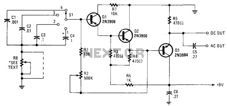
Seven narrow pulses ranging from 2 Hz to 50 kHz are generated by this circuit. Capacitors C1 through C4 provide frequency ranges in decode steps. Resistors R1 and R2 regulate the charging time of capacitors C1 through C4. R2...
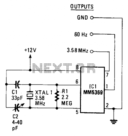
The circuit generates a clean, stable square wave and operates within a voltage range of 6 to 15 volts. The integrated circuit (IC) and color-burst crystal utilized are commonly found in television receivers. The output frequency of 3.58 MHz...
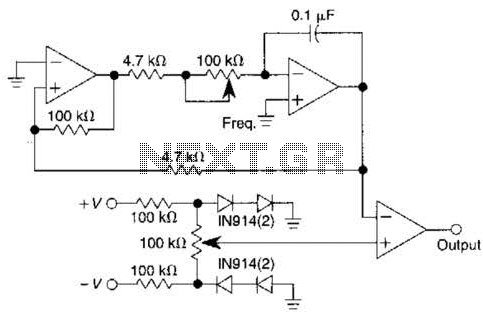
This pulse generator utilizes a single integrated circuit (IC) and six passive components to achieve a frequency range of 400 to 4000 Hz, with an adjustable duty cycle ranging from 1% to 99%. The circuit employs a threshold detector...
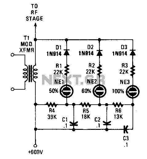
Switching diodes are utilized to activate the neon lamps when negative-peak modulation reaches 50%, 60%, and 100%. To operate the circuit effectively, it is important to monitor the lamps. The 50% lamp should ideally be firing continuously, the 60%...
The circuit utilizes two white LEDs, with the second LED connected across the emitter of the transistor and the negative ground. It requires its own limiting resistor in series, similar to R15 and D3 in the circuit diagram. If...
The Smart Ballast IC is designed to control a fluorescent lamp ballast, including a Discontinuous Conduction Mode Power Factor Correction (PFC), lamp inverter control, and a high voltage level shift half-bridge driver. The application requires a minimum number of...