
60Hz pulse generator

The circuit design features a square wave oscillator that leverages a color-burst crystal, typically resonating at 3.58 MHz, which is a standard frequency used in television broadcasting. This frequency is particularly advantageous for applications in shortwave radio, where it can be employed as a reference signal or marker for tuning purposes.
Power supply considerations are crucial, as the circuit is designed to function effectively between 6 to 15 volts. This flexibility allows it to be integrated into various electronic systems without the need for extensive modifications. The IC used in the circuit is selected for its reliability and performance in generating stable oscillations, ensuring that the output remains consistent even with variations in supply voltage.
The output square wave can be utilized in multiple applications beyond shortwave radio, including signal processing and synchronization tasks in digital circuits. The clean nature of the square wave minimizes distortion, making it suitable for interfacing with other electronic components or systems.
Overall, this circuit serves as a versatile tool for generating a precise frequency signal, with applications across various fields of electronics, particularly in radio communications and television technology.The circuit provides a clean, stable square wave and it will operate on anywhere from 6 to 15 volts. The IC and color-burst crystal are the kind used in TV receivers. The 3.58 MHz output makes a handy marker signal for shortwave bands.
Related Circuits

Building a signal generator is an essential project for any analog DIY enthusiast. While already possessing a bench signal generator, the intention was to create a compact, battery-powered device for quickly testing new effect designs. An enclosure from a...
The circuit depicted in the figure allows for the selection of optimal operating conditions and a suitable allocation of the temperature coefficient for the resonant circuit components. The resonance occurs at both ends of the circuit. Additionally, the exchange...
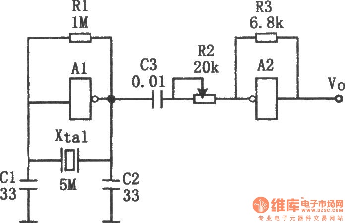
The sine wave generator composed of an inverter is illustrated in the chart. This circuit can produce a high-stability sine wave at frequencies exceeding a few megahertz. In the diagram, A1 and the crystal oscillator create an oscillating circuit,...
This simple circuit generates narrow pulses at about 700-800Hz frequency. The pulses, containing harmonics up to the MHz region, can be injected into audio or radio-frequency stages of amplifiers, receivers and the like for testing purposes. A high-pitched tone...

In this TMOS pulser, a negative-going pulse is applied to U1, a high-speed CMOS buffer, which directly drives the gate of Q1, an MTP3N35. If only a 100-V pulse is required, the MTA6N10 can be used. The pulse output...
The telephone ring generator shown below generates the needed high voltage from a simple switching mode power supply (SMPS) which employs a CMOS Schmitt Trigger square wave oscillator, 10 mH inductor, high voltage switching transistor (TIP47 or other high...