
Pulse Width Modulation DC Motor Control
Pulse Width Modulation (PWM) is an efficient method for controlling the speed of DC motors. In a typical PWM circuit for a DC motor, a microcontroller or timer IC generates a square wave signal with a specific frequency. The duty cycle of this square wave—the ratio of the time the signal is high to the total time period—determines the average voltage supplied to the motor.
The circuit typically consists of a microcontroller (such as an Arduino or PIC) that outputs a PWM signal through a digital pin. This signal is then fed into a transistor, which acts as a switch. The transistor can handle higher currents than the microcontroller pin can provide, allowing it to control the motor directly. A common choice for the transistor is an N-channel MOSFET, which is efficient and capable of switching quickly.
The motor is connected to the collector (or drain) of the transistor, with the other terminal connected to the power supply. A flyback diode is placed in parallel with the motor to protect the circuit from voltage spikes generated when the motor is turned off. This diode allows the current generated by the inductive load of the motor to safely dissipate.
The frequency of the PWM signal is typically set between 1 kHz and 20 kHz, depending on the application and motor specifications. A higher frequency can lead to smoother motor operation, while a lower frequency may result in audible noise from the motor. The duty cycle can be adjusted programmatically to achieve the desired speed. For example, a 100% duty cycle provides full power to the motor, while a 50% duty cycle effectively halves the power, resulting in a slower motor speed.
In summary, the PWM method for DC motor control offers a significant advantage over traditional variable resistor methods by minimizing power loss and heat generation, thus enhancing efficiency and extending the lifespan of the motor and associated components.Often, people attempt to control DC motors with a variable resistor or variable resistor connected to a transistor. While the latter approach works well, it generates heat and hence wastes power. This simple pulse width modulation DC motor control eliminates these problems. It controls the motor speed by driving the motor with short pulses. These pulses vary in duration to change the speed of the motor. The longer the pulses, the faster the motor turns, and vice versa. 🔗 External reference
Related Circuits
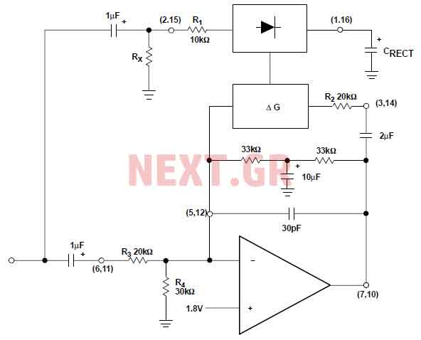
The NE570 can be used to make a high performance compressor FTA, except that the rectifier is connected to the input. This makes gain inversely proportional to the input level so that a drop of 20 dB input level...
The layout control motherboard is designed to facilitate the management of various sections of a layout. It features a microcontroller that connects to the MRNet bus and multiple slots for inexpensive control and sensor boards. All control and sensor...
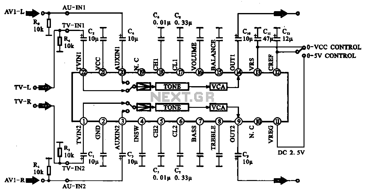
Audio signal control circuit. It illustrates a typical audio signal control circuit where two audio signals enter the integrated circuit through switching and tone controls (treble and bass), subsequently adjusting the output sent to the audio power amplifier. The audio...
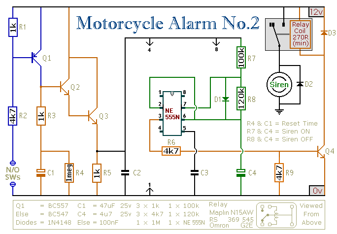
This circuit provides an intermittent siren output with an automatic reset function. It can be manually activated using a key switch or a concealed switch, and it can also be configured to engage automatically when the ignition is turned...
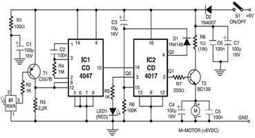
The following circuit illustrates an infrared toy car motor controller. This circuit is based on the 4047 and 4017 integrated circuits (ICs). Features: 16V. The infrared toy car motor controller circuit utilizes two primary integrated circuits, the 4047 and the...
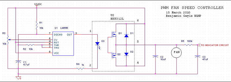
A fan speed controller for computer fans consists of two sections: one for manual speed control and another for automatic temperature-dependent speed control. Additionally, there is a section for a simple LED output indicator. While it is common to...