
Audio signal control circuit

The audio signal control circuit serves as a crucial component in audio processing systems, allowing for the manipulation of sound signals before amplification. This circuit typically consists of an integrated circuit (IC) that incorporates various functionalities, including input switching, tone adjustment, and output control.
In this configuration, two audio signals are fed into the IC, which can be selected based on user preference or system requirements. The switching mechanism is often implemented using analog switches or digital multiplexers, enabling seamless transitions between the audio sources without introducing noise or distortion.
Once the desired audio source is selected, the signal passes through tone control stages where treble and bass adjustments are made. These adjustments are typically achieved using passive components such as capacitors and resistors, or through active components like operational amplifiers configured in tone control circuits. The treble control adjusts the higher frequency response, enhancing or attenuating specific ranges, while the bass control modifies lower frequencies, allowing users to tailor the audio output to their liking.
After the tone adjustments are completed, the processed audio signal is then sent to an audio power amplifier. The amplifier's role is to increase the signal's power level to drive speakers or other output devices effectively. The output stage may include additional filtering to ensure that the final audio signal is free from unwanted noise and distortion, providing a clean and high-quality sound experience.
Overall, this audio signal control circuit is essential for achieving optimal sound quality and user satisfaction in various audio applications, from home theater systems to professional audio equipment.Audio signal control circuit It shows a typical audio signal control circuit. Two audio signal into the integrated circuit through the switching and tone (treble, then adjust the output sent to the audio power amplifier bass).
Related Circuits
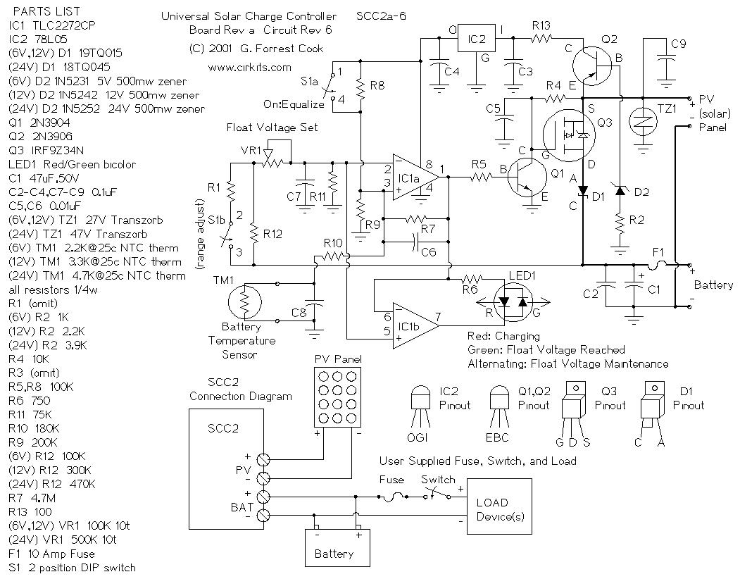
The SCC2 is a solar charge controller designed to manage the power transfer from a photovoltaic panel to a rechargeable battery. It includes a straightforward setup process utilizing a single potentiometer for adjusting the float voltage, an equalization function...
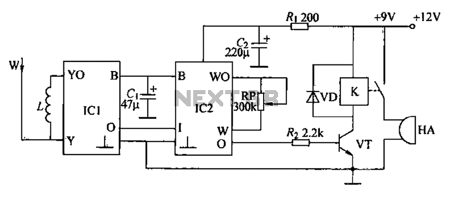
A circuit for an inductive burglar alarm is derived from a radio scanning detection circuit, which includes a signal processing circuit and an alarm circuit. The radar detection circuit module consists of components such as microwave emission, low-pass filtering,...
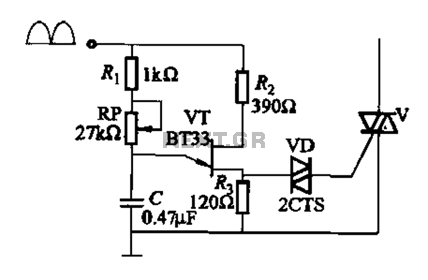
Figure 16-29 (a) illustrates the trigger output through a resistor R2, while Figure 16-29 (b) depicts the integration of a programmable unidirectional transistor (PUT) trigger circuit. The adjustable potentiometer RP can modify the conduction angle of the TRIAC to...
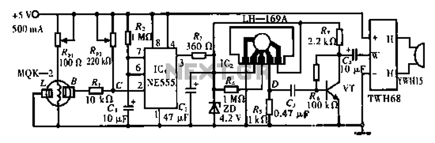
The circuit operates using the MQK-2 gas sensor, which detects the presence of combustible gases or smoke through surface adsorption. When gas is detected, the inter-electrode resistance (BL) decreases significantly. This change in resistance affects the voltage at node...
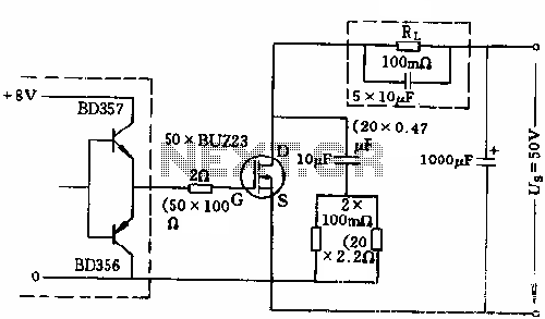
The circuit employs 50 BUZ23 field effect transistors (FETs) arranged in parallel, with a tube blocking voltage of 100V. The control power required is minimal, eliminating the risks associated with second breakdown and the positive temperature coefficient phenomenon in...
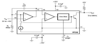
The circuit diagram of a voltage-to-frequency (V/F) converter is presented, designed to handle negative input voltage. It employs the VFC32 voltage-to-frequency converter, which is commonly utilized in various applications. The V/F converter circuit is essential in converting an analog voltage...