
Pulse-width modulator

The monostable circuit, commonly known as a one-shot multivibrator, is designed to produce a single output pulse in response to a triggering input. In this configuration, the circuit is triggered by a continuous pulse train, which serves as the input signal. The threshold voltage, a critical parameter in determining the output pulse characteristics, is modulated by an external control signal. This modulation allows for dynamic adjustment of the pulse width, which is the duration of the output signal.
The output pulse width can be varied based on the amplitude and frequency of the control signal. The circuit's response to the input pulse train results in a controlled output that can be tailored for various applications, such as timing circuits, signal processing, or pulse width modulation systems. The modulation signal can take various forms; while a sine wave is illustrated as an example, other waveforms, such as square waves or triangular waves, can also be employed depending on the specific requirements of the application.
In practical implementations, the monostable circuit typically consists of components such as resistors, capacitors, and a triggering device (like a transistor or an operational amplifier) that define the timing characteristics. The resistor-capacitor (RC) time constant plays a pivotal role in determining the output pulse width, which is influenced by the control signal. The design must ensure that the circuit is stable and responsive to the input signal while providing the desired modulation effect.
Overall, the versatility of the monostable circuit allows it to be integrated into a wide range of electronic systems, enhancing functionality through precise control of pulse characteristics.The monostable circuit is triggered by a continuous input pulse train and the threshold voltage is modulated by a control signal. The resultant effect is a modulation of the output pulse width, as shown A sine-wave modulation signal is illustrated, but any wave-shape could be used.
Related Circuits
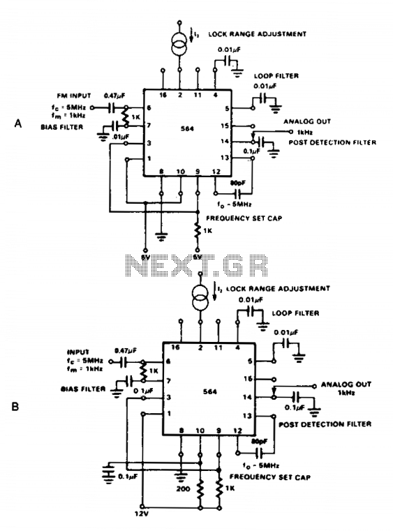
The NE564 functions as an FM demodulator. The operational connections for both 5 V and 12 V configurations are illustrated in Figures 21-4A and 21-4B. The input signal is AC coupled, with the output signal extracted from Pin 14....
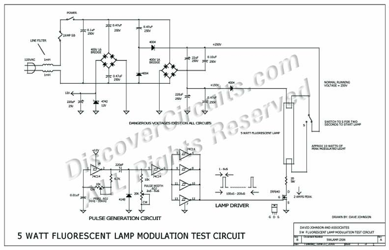
The circuit was designed to experiment with using small fluorescent lamps as a broad pattern source of modulated light. The circuit delivers narrow 1 μs pulses to the small lamp at a frequency of 10 kHz. Each pulse generates...
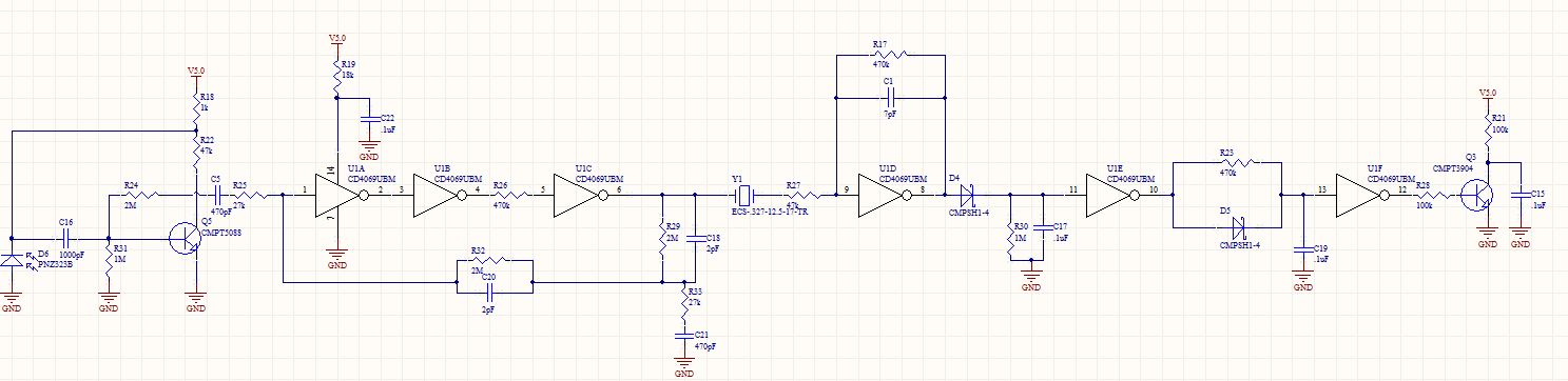
The circuit receives a 32.768 kHz infrared (IR) input and produces a logic low output when the input signal is detected. The design consists of three distinct stages: the section up to U1A, the section between U1A and Q3,...
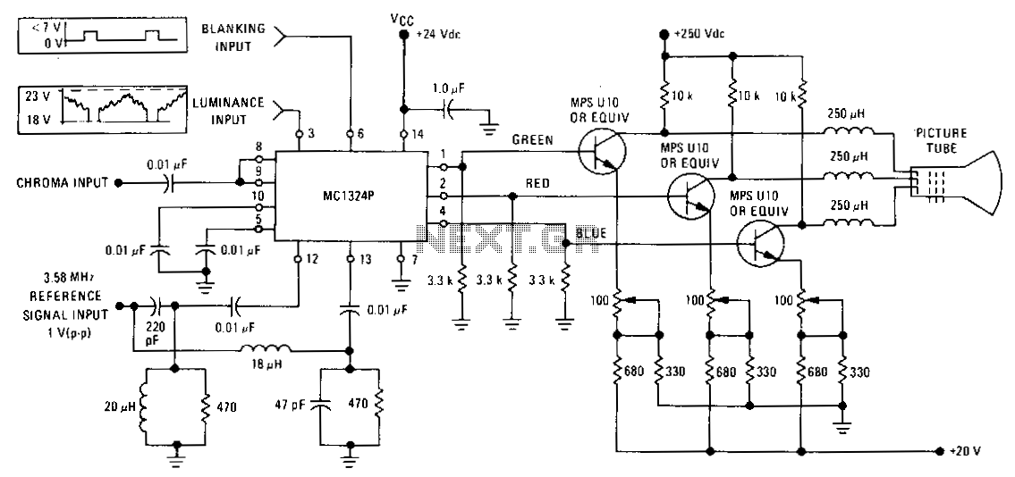
The MC1324 provides chroma demodulation, recovering the R, G, and B signals to drive video amplifiers for each color difference signal. The luminance signal and chrominance signal are matrixed to obtain the R, G, and B signals. The MC1324 is...
The AN7415 is a monolithic integrated circuit designed for FM stereo demodulation applications. It operates within a voltage range of 1.6 to 7 V DC, making it suitable for handheld FM radios powered by two AA dry cells. This...
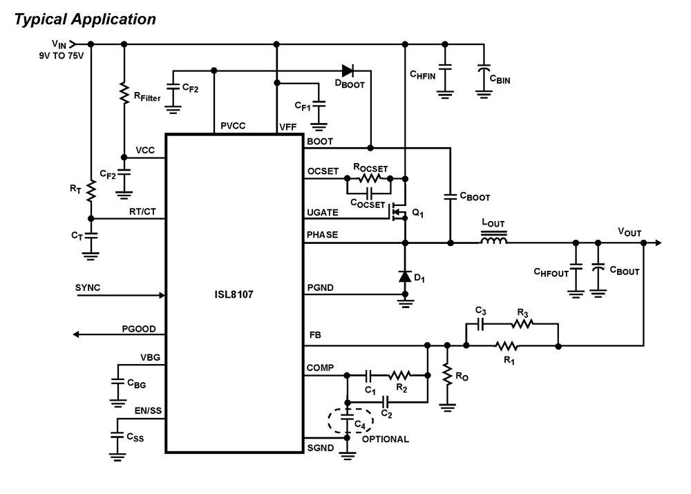
The ISL8107 is a single-phase, non-synchronous buck controller equipped with an integrated high-side MOSFET driver. It operates within an input voltage range of 9V to 75V. The internal reference voltage is 1.192V with a tolerance of ±1% across the...