
Pulsed infrared diode circuit

In this circuit configuration, transistors Q1 and Q2 are utilized to establish a constant current source, effectively regulating the output current based on the resistor R2. The operation of the circuit is such that when the current exceeds 1 amp, the relationship between the current and R2 can be approximated as I = 1/R2, indicating that the current is inversely proportional to the resistance value.
Capacitor C1 plays a crucial role in the circuit by providing pulse current. The charging and discharging cycles of C1 are critical for maintaining the desired output characteristics. The recharging of C1 occurs through resistor R1 during the intervals between the current pulses. The value of C1 is selected based on the specific requirements of the application, particularly the peak current magnitude and the duration for which this peak current is needed.
The time constant of the circuit, defined by the product of R1 and C1 (τ = R1C1), dictates the response time of the circuit and the duration between the pulses. A longer time constant results in a slower response, which may be suitable for applications requiring longer intervals between pulses, while a shorter time constant allows for quicker transitions, catering to applications demanding rapid pulse sequences.
This configuration is commonly applied in various electronic applications, including signal modulation, pulse width modulation (PWM) control, and other scenarios where precise current control is essential. The design ensures that the circuit can efficiently handle the specified requirements while maintaining stability and performance across a range of operating conditions.Ql and Q2 form a constant current drive defined by R2. (I approximates to the reciprocal of R2 in the circuit shown for values of I greater than 1 amp). The pulse current is drawn from Cl which is recharged during the time between pulses via Rl. The value of Cl is determined from the duration and magnitude of the peak current required, and the time constant Rl Cl is determined from the duration between pulses.
Related Circuits
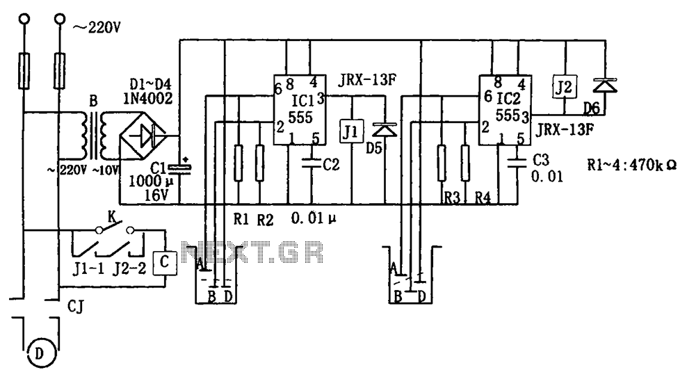
The level control circuit comprises a step-down rectifier circuit, a trigger circuit utilizing two 555 timer ICs (IC1 and IC2), and a relay control circuit. The rectifier circuit is responsible for providing the necessary DC voltage for the flip-flop...
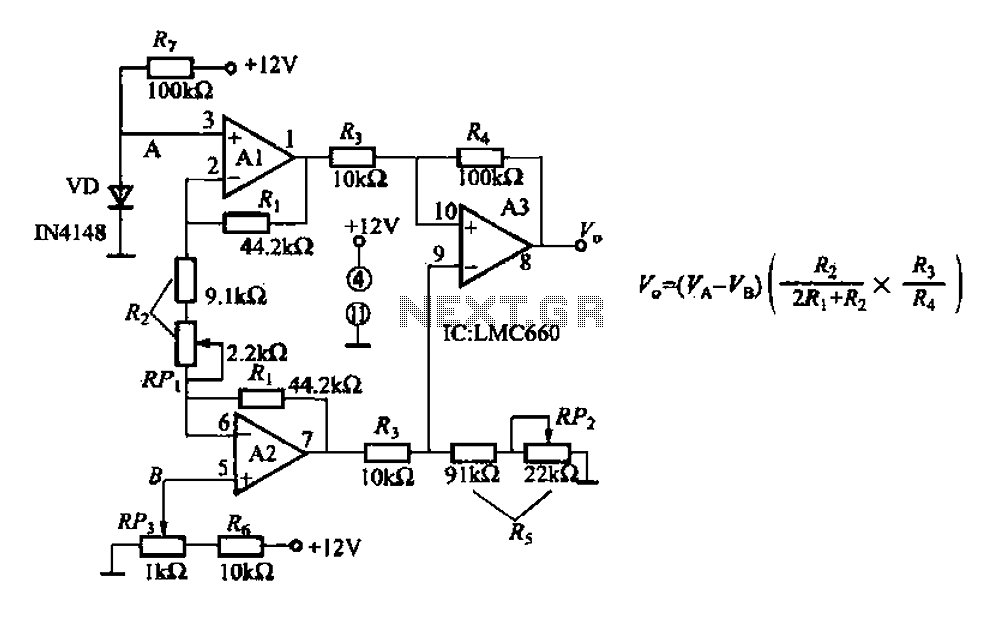
A diode IN4148 temperature circuit is presented. The circuit operates within a temperature range of -25 to 125 degrees Celsius, with an accuracy of 0.5. The core components of the operational amplifier circuit consist of four LMC660 amplifiers. It...
This version sports a 2nd audio amplifier stage at Q3. The output level with this version is sufficient to drive a crystal headphone to a comfortable volume. The "crystal" headphone is like those used on ye olde crystal radios....
Load current starts approximately 0 RC after the switch is thrown. The statement indicates that the load current begins at approximately 0 ohms after a switch is activated. This scenario is common in electronic circuits where a switch controls the...

RS-232 Serial Interface Status Indicator Circuit. This circuit utilizes a single logic integrated circuit (IC) to indicate the transmission (TXD) and reception (RXD) statuses of a serial interface. The RS-232 Serial Interface Status Indicator Circuit is designed to provide visual...
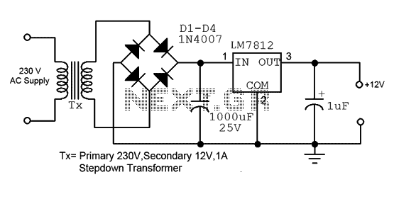
This is a straightforward 12V power supply circuit diagram. It features a fixed voltage output and is based on the LM7812 voltage regulator integrated circuit. The 12V power supply circuit utilizing the LM7812 voltage regulator is designed to provide a...