
12V fixed voltage power supply circuit diagram

The 12V power supply circuit utilizing the LM7812 voltage regulator is designed to provide a stable output voltage of 12 volts, making it suitable for various electronic applications. The LM7812 is a linear voltage regulator that offers ease of use and reliability.
The circuit typically consists of the following components: an input capacitor, the LM7812 voltage regulator, and an output capacitor. The input capacitor is placed at the input pin of the LM7812 to filter any high-frequency noise from the power supply, ensuring a clean voltage supply. The output capacitor is connected to the output pin of the regulator to improve transient response and stability.
The input voltage to the LM7812 should be higher than 12V, typically in the range of 14V to 35V, to allow for proper regulation. The LM7812 can handle output currents up to 1A, making it suitable for powering low to moderate power devices.
Thermal management is also a crucial consideration in the design of this circuit. The LM7812 can dissipate heat during operation, especially when the input-output voltage differential is significant. Therefore, a heat sink may be required to prevent the regulator from overheating and to ensure reliable operation.
Overall, this simple 12V power supply circuit is an effective solution for providing a stable voltage output for various electronic projects and applications.This is a simple 12v power supply circuit diagram. It has a fixed voltage output and it based on LM7812 voltage regulator IC.. 🔗 External reference
Related Circuits
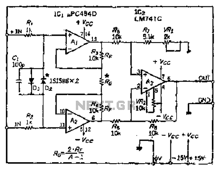
All resistance values are equal, resulting in the Cantonese operational amplifier's gain (A) being equal to 1. However, by selecting smaller resistances, the gain can be adjusted. The circuit can achieve the desired gain through six configurations. Two heavy...
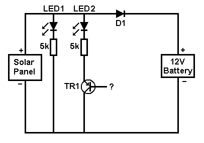
A small solar panel is used to maintain a 12V car battery. The panel provides approximately 75mA of current to the battery under full sunlight conditions. The described circuit employs a solar panel specifically designed for battery maintenance applications. The...
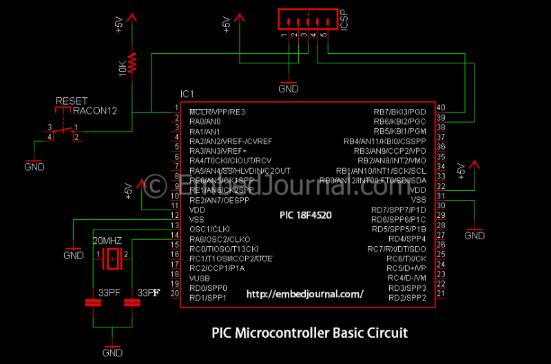
PC parallel port can be very useful I/O channel for connecting your own circuits to PC. The PC's parallel port can be used to perform some very amusing hardware interfacing experiments. The port is very easy to use when...
This is a line follower designed to trace grid-type tracks. It features five line sensors for tracking the line. This arrangement of five sensors has proven effective, having been used multiple times with successful results. The device is named...
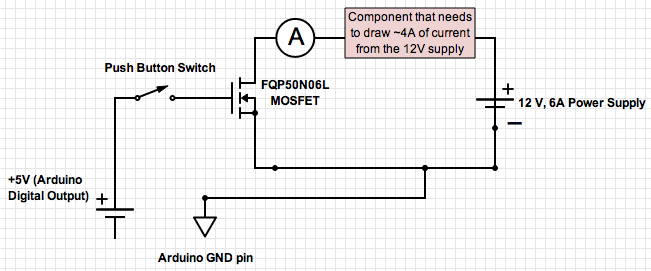
If the ground of the Arduino is disconnected from the negative terminal of the power supply, current flows through the MOSFET, even when the switch is not closed. In an electronic circuit involving an Arduino and a MOSFET, maintaining a...
The working principle involves two pairs of photoelectric detection devices installed in the access channel. One side features light source A (transmitter) and photoresistor LDR1 (receiver) at the entrance of the channel, while the other side contains light source...